 PRIME MOTION
Choosing tools for a toolpath
Every operation needs a cutter. The choice decides how the toolpath is generated, not just what cuts it — the tool's diameter determines where a contour can run, what a pocket can reach into, and how fine a finish is possible.
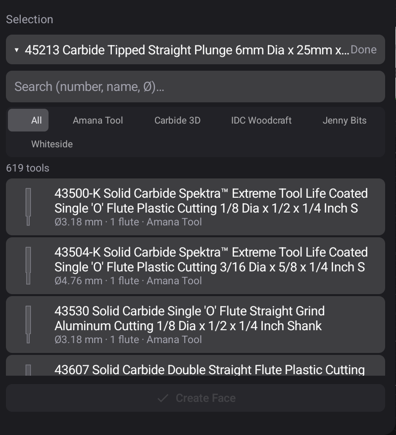
Tools come from the tool library. Every operation panel carries a Tool Library section: the current selection, and a picker over the whole catalog — searchable by number, name or Ø, filterable by vendor.
What the tool brings with it
Selecting one carries its whole description into the operation:
Geometry — diameter, flute length, shaft, tip angle. This is what the toolpath is calculated against, and what shapes the cutter you see in simulation and on the Run screen.
Speeds and feeds — the manufacturer's published spindle speed, cutting feed, and separate rates for plunging, ramping, lead-in and lead-out.
Diameter is a design decision
A cutter cannot machine an internal corner smaller than its own radius. Choose a 6 mm endmill and every inside corner in the part will be 3 mm radius, whatever the model says.
Big for roughing, small for finishing
The usual pattern, and it holds almost everywhere:
Roughing with the biggest cutter that fits the job. It removes material faster, tolerates deeper passes, and does not care about the finish it leaves.
Finishing with a smaller one that can reach the detail, taking light passes.
Cleanup with something smaller still, only where the finishing tool could not reach.
Three operations with three tools is usually faster and better than one operation trying to do all three jobs.
Collets
A tool has to fit the collet you own. The library can filter by collet, which turns a list of several hundred cutters into the ones your spindle can actually hold — see Browsing a library.