 PRIME MOTION
Tutorial: a parametric fixture plate
This tutorial builds a real part from nothing: an aluminium or hardwood fixture plate you could bolt to a spoilboard. Along the way it touches every stage of the app once, in the order you will use them on your own parts:
- a new design, named and filed;
- Parameters that hold the sizes you will want to change later;
- a sketch, sized by those parameters;
- 3D features: an extrude, a counterbore and a chamfer;
- a Tool Run with stock and a work zero;
- toolpaths, a simulation, and a posted program;
- an Outline check, an Air Run, and a cut on your machine.
What you will make
| Feature | Size |
|---|---|
| Plate | 120 mm long (X) × 80 mm wide (Y) × 12 mm thick |
| Centre bore | Ø40 mm, through |
| Counterbore around it | Ø56 mm, 6 mm deep |
| Mounting holes | 4 × Ø6.6 mm through, Ø11 × 6.5 mm counterbores, 15 mm in from each edge |
| Top edges | 1 mm chamfer |
1 · Start a design
Designs live in the Designs panel on the Design tab. With no design open it fills the left of the screen.
- Tap Design in the bottom bar.
- Open the folder you want the design in. This tutorial uses a folder called Showcases.
- Tap the folder's name in the breadcrumb (here Showcases ⌄) and choose New design.
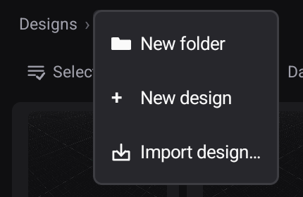
The new design opens straight away, empty, with the Design, Manufacturing and Parameters workspace tabs across the top.
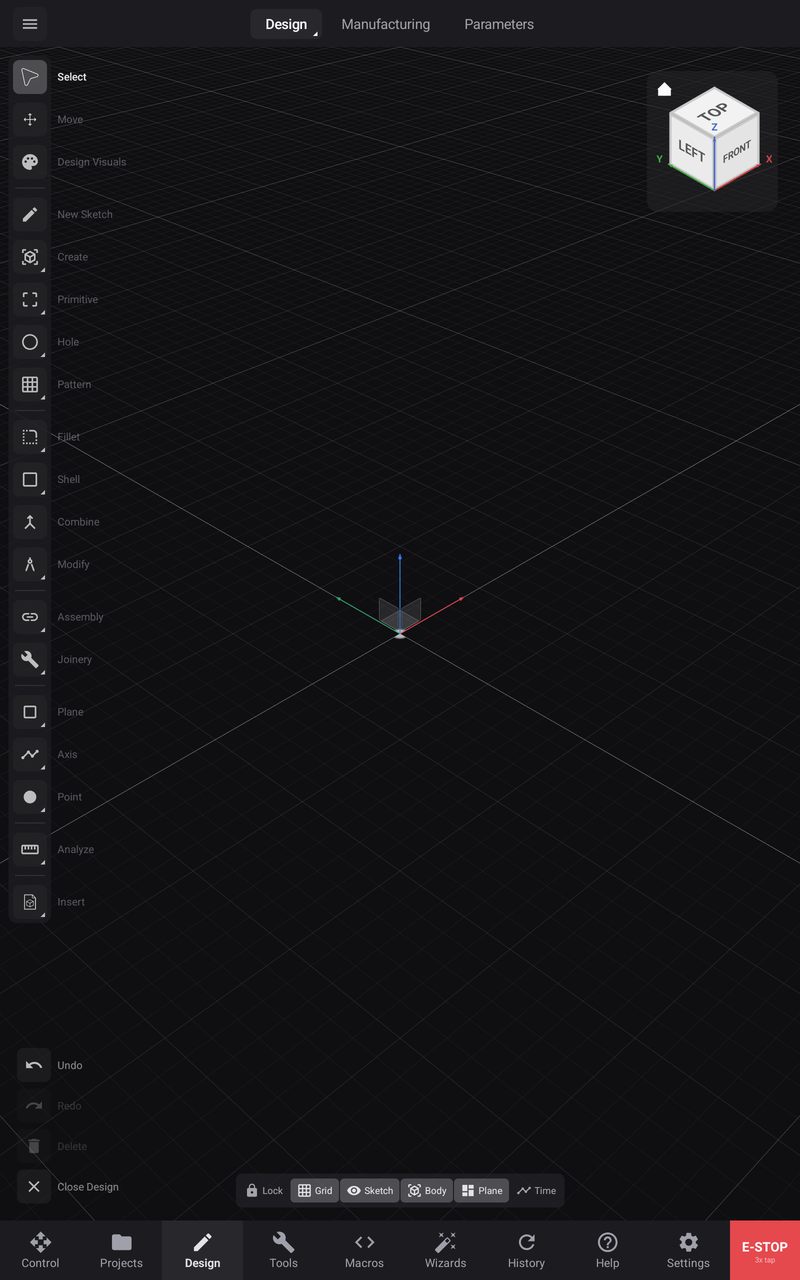
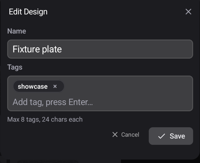
It is called Design 1 (or the next free number). Give it a real name now, so you can find it later: close it with Close Design at the foot of the rail, tap the design's ⋮ in the Designs panel, choose Edit, type Fixture plate, add a tag if you like, and tap Save. Then tap the tile to open it again.
2 · Decide what can change: Parameters
Before drawing anything, decide which sizes you might want to change later. A fixture plate is a good example: next month you may want the same plate in 15 mm stock, or 20 mm longer. If those sizes are parameters, changing one number rebuilds the part. Check affected toolpaths afterwards; operations marked stale need to be regenerated before you post them again.
- Tap the Parameters tab at the top.
- Tap + Parameter. A new row appears with its name selected; type plate_length and tap Done on the keyboard.
- Tap the row's Expression cell, type 120, and tap Done.
- Repeat for plate_width = 80, plate_thickness = 12 and hole_inset = 15.
- Tap each Comment cell and say what the number is for. You will thank yourself in six months.
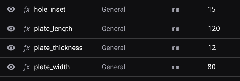
Rows sort by name, so a new row may jump into place as soon as you name it. Check that each value landed on the row you meant before moving on.
3 · Sketch the plate's outline
A sketch is a flat drawing on a plane. Everything 3D in this plate starts from one sketch on the XY Top plane, which is the plane the machine's table is parallel to.
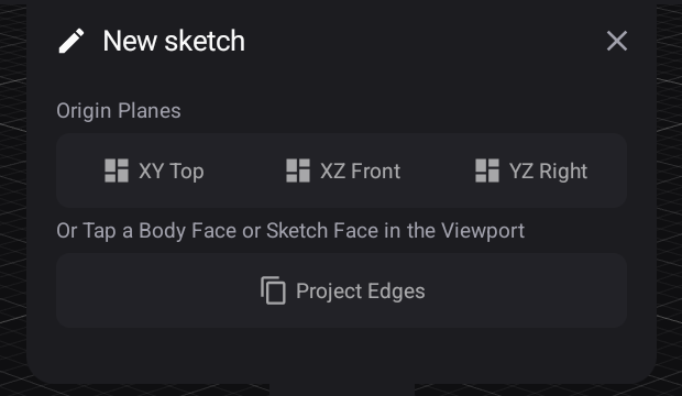
- Tap the Design tab, then New Sketch in the rail.
- In the New sketch drawer, tap XY Top. The view turns to look straight down and the rail changes to the sketch tools.
Draw the rectangle
- Long-press the rectangle button in the rail and choose Center Rectangle.
- With the pen, press where the middle of the plate should be and drag out to a corner. Lift the pen. Size does not matter yet; the parameters will set it.
- Check the Horizontal and Vertical constraint marks on the new rectangle. They align its sides with the sketch axes automatically.
Size it from the parameters
A dimension that names a parameter is a promise: whenever the parameter changes, the sketch follows.
- Tap Dimension in the rail, then tap the top edge. The dimension keypad opens with the edge's current length.
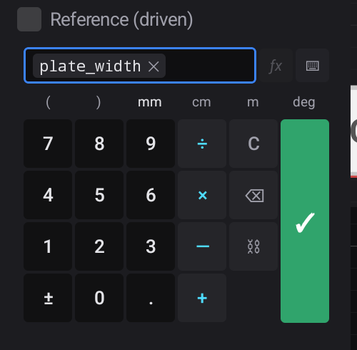
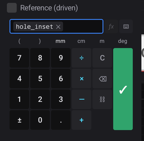
- Tap ƒx, open General, and tap plate_length. The value becomes the parameter's name.
- Tap the green ✓. The edge snaps to 120 mm.
- Choose Select, then Dimension again. Tap the left edge and bind it to plate_width. Starting a fresh dimension avoids asking for the angle between two edges.
Optional: centre the plate on the origin
Choose Coincident, tap the Center Rectangle's centre marker, then the sketch origin. The whole outline moves to zero while keeping its width and height. Use the real centre marker rather than a point placed by eye; the construction diagonal helps you find it.
4 · Locate the centre bore
The bore belongs in the middle of the plate. Express that position with constraints rather than trying to draw it accurately by eye.
- Choose Center Diameter Circle and draw a circle inside the rectangle.
- Use Dimension to set its diameter to 40 mm.
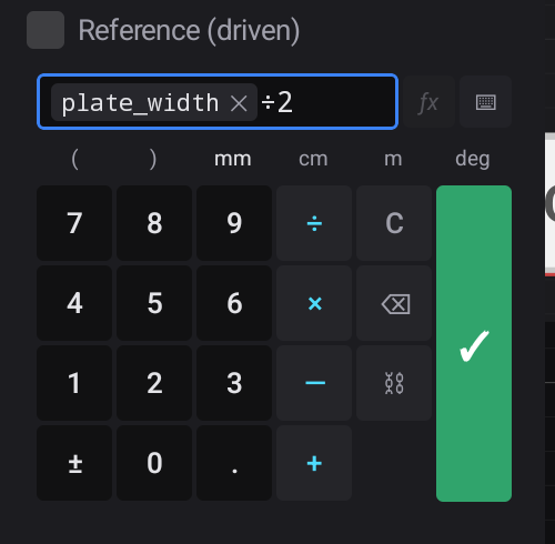
- Use Distance between its centre and the left edge; enter plate_length/2.
- Set the distance from the same centre to the bottom edge to plate_width/2.
- Choose Finish Sketch. The mounting holes will use Hole's point placements after extrusion.
Pick near the middle of a straight edge to distinguish it from a corner. If a constraint is still holding its first pick, choose Select and start that constraint again.
5 · Make the plate solid
- Open Create → Extrude.
- Pick the plate region between the rectangle and the circle. The circle must remain a hole in the preview; selecting its filled region would make a cylinder instead.
- Set the distance to plate_thickness using the expression keypad's ƒx list.
- Choose New Body and apply the extrude.
- Orbit the view and check for shaded top and side faces and the centre bore. A sketch outline alone is not a solid body.
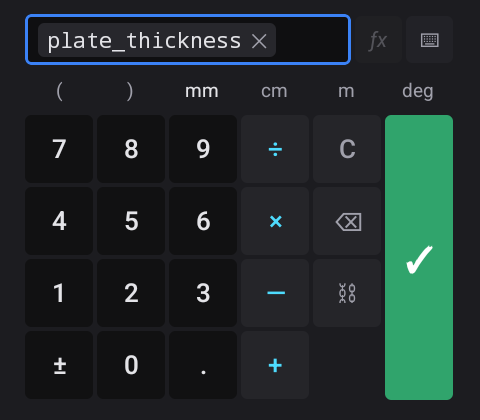
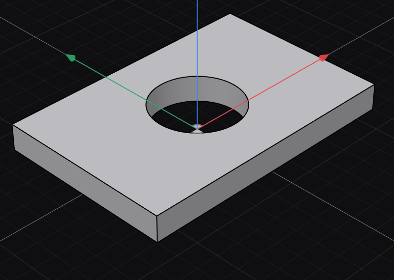
The extrusion is bound to a parameter rather than a copied number. Changing plate_thickness will therefore change the solid's thickness too.
6 · Add counterbores with Hole
A counterbore is a larger, shallow opening around a smaller through hole. Hole gives its diameter and depth separate fields.
- Choose Hole and pick the plate's top face.
- Leave Points empty to use the centred face's default placement.
- Choose Counterbore. Enter Diameter 40 mm, Counterbore Ø 56 mm, and Counterbore depth 6 mm. Choose Thru-All for the smaller bore.
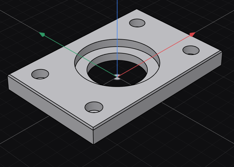
- Tap Hole. Inspect the result: the Ø56 recess has a floor halfway through the 12 mm plate, while the Ø40 bore continues through it.
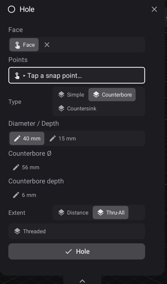
Place four mounting holes together
- Open New Sketch, enable Project Edges, then pick the top face. Its outside boundary appears in the sketch.
- Place four sketch Point entities near the corners. Keep the edges clear of the tool rail while picking; zoom out slightly if the rail covers the left side.
- For each point, use Distance to each of its two nearest projected edges and enter hole_inset. That makes eight 15 mm distances.
- Choose Finish Sketch and turn the viewport's Sketch chip on so the points show.
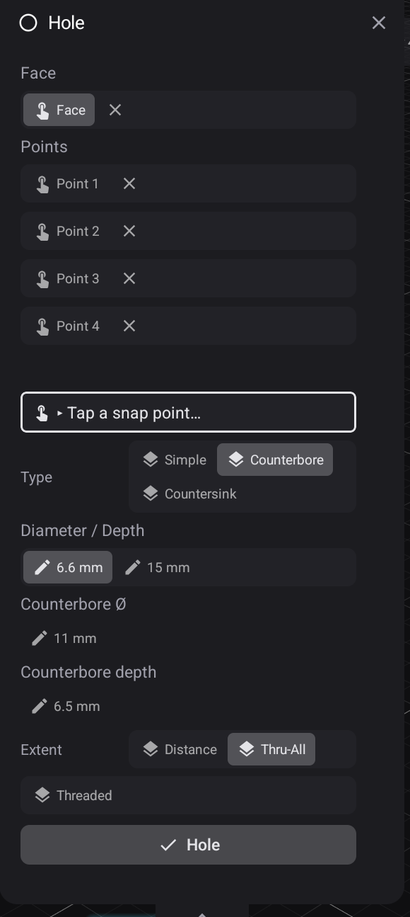
- Choose Hole, pick the top face, then the four points. Check Point 1 through Point 4 in the drawer; remove an incorrect pick with its ×.
- Choose Counterbore, Diameter 6.6 mm, Counterbore Ø 11 mm, Counterbore depth 6.5 mm, and Thru-All. Tap Hole.
- Inspect all four stepped holes. One Undo removes the pattern; Redo restores it.
Try Project and Concentric
For a reference sketch, project the Ø40 body edge, draw another circle, and make it Concentric with the projected circle. Dimension it to 56 mm. A circle-centre Distance to a projected outside edge also works. Hole already made the recess, so finish this reference sketch without cutting it again.
Chamfer the top edges
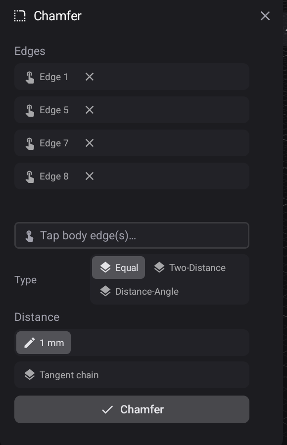
Choose Chamfer from the fillet family. Pick the four outside top edges and check all four highlight while the distance is 0 mm. Enter 1 mm and apply. The chamfer removes the sharp outside corner without rounding away the plate's flat top.
Check a parameter edit before making toolpaths
- In Parameters, change plate_thickness from 12 to 15 and wait for the model to finish updating.
- Open Design. Check the shaded plate, the central stepped bore and all four mounting holes.
- Choose Undo to return to 12 mm, then Redo to restore 15 mm. Check the openings after each.
- Close and reopen the design. Check that plate_thickness is still 15 and all five openings remain in the shaded body.
- Restore plate_thickness to 12, close and reopen again, and check the value and body before continuing with the stock setup below.

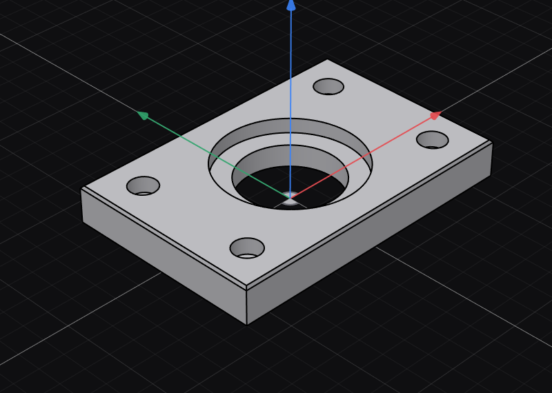
Make this check before committing time to machining. It confirms that the dimension you intend to vary really drives the part. Timeline explains editing and undoing features; Parameters explains expressions and their referrers.
7 · Define stock and a work zero
The design describes the finished part. A Tool Run adds the blank you will cut it from, the machine profile and the work zero used by its operations.
- Open Manufacturing → Tool Run.
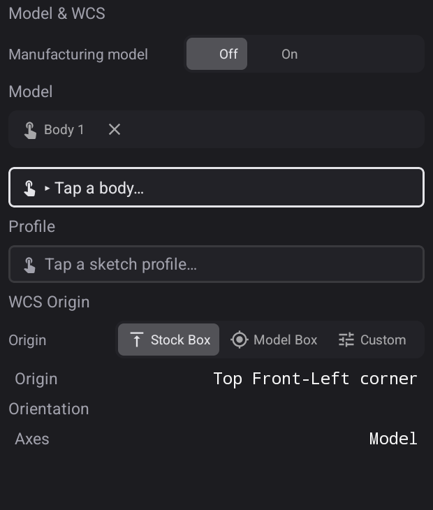
- Under Geometry → Model & WCS, tap Tap a body…, then tap the plate's top face. Confirm Body 1 appears as a selected model.
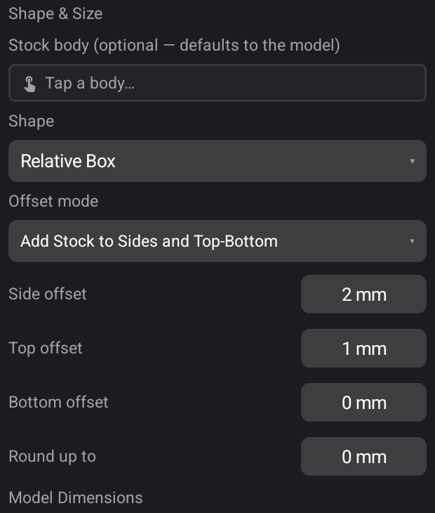
- Under Stock → Shape & Size, choose Relative Box. Set Side offset to 2 mm, Top offset to 1 mm, and Bottom offset to 0 mm.
- Return to Geometry → Model & WCS, choose Stock Box, and tap the stock's top front-left corner glyph in the view. Check that the readout says Top Front-Left corner.
- Under Program → Naming, name the run Plate Top and select G54.
- Under Program → Machine, check the intended machine profile, then choose Create Tool Run.
Pick the stock corner in the view; the origin's text is a readout. That corner is a place you can locate on a real blank. Its top is 1 mm above the finished plate, so the first operation will remove that allowance. G54 must later be set to the same physical corner in Control.
See Stock and setups for other stock shapes and origins.
8 · Choose a cutter deliberately
For this example, select the Amana Tool 45213, a 6 mm straight plunge cutter, in each operation's Tool Library → Selection. Star it in the selector, open Favorites, and choose it there. Favorites is a shortcut to your chosen tool, not an automatic tool choice.
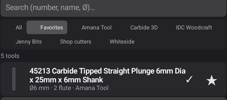
The cutter fits the Ø6.6 holes with room for a small circular motion. The example uses one tool for all six operations; the Ø40 bore uses clearing motions rather than a 40 mm drill.
9 · Create the six operations
Create the operations in the following order. Each one should show a valid selection and a preview before you choose its Create button.
Face the top
- Open 2D → Face and pick the actual top face of the plate. Hide the sketch with the viewport's Sketch chip if its curves intercept your pick.
- Select the 6 mm tool through Favorites.
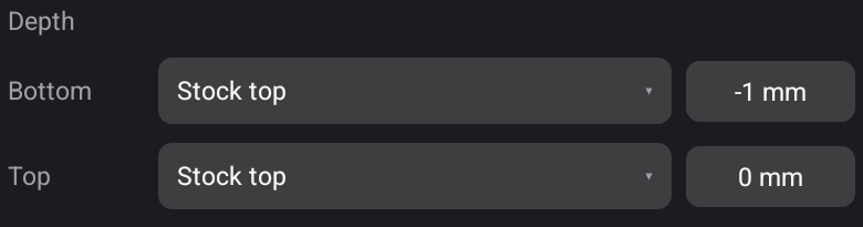
- Under Heights → Depth, set Top to Stock top, offset 0 mm, and Bottom to Stock top, offset −1 mm.
- Choose Create Face.
This removes the 1 mm top allowance. Check that the preview covers the whole plate, rather than only the circular recess.
Pocket the counterbore
- Open 2D → 2D Pocket and select the Ø56 circular body edge as the boundary. The Ø40 bore edge is a different boundary; remove its selection chip if you picked it by mistake.
- Select the 6 mm tool.
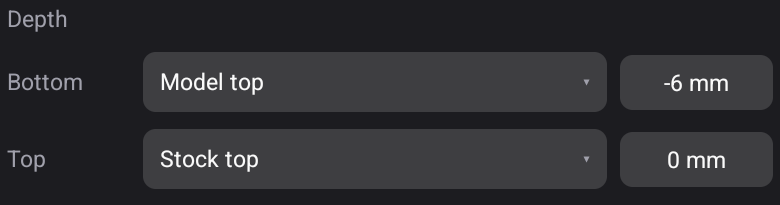
- Set Top to Stock top, offset 0 mm, and Bottom to Model top, offset −6 mm.
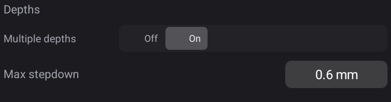
- Under Passes → Depths, turn Multiple depths on and set Max stepdown to 0.6 mm.
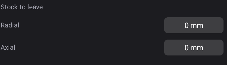
- Under Passes → Stock to leave, set both Radial and Axial to 0 mm.
- Choose Create Pocket.
Using Model top for the bottom states the recess depth relative to the finished plate. Do not interpret a height offset as a distance down from whatever happens to be visible on screen.
Pocket the four mounting counterbores
- Create another 2D Pocket and pick the four Ø11 circular mouth edges.
- Check four separate regions, select the 6 mm tool, and inspect their previews.
- Set Top to Stock top, offset 0 mm, and Bottom to Model top, offset −6.5 mm.
- Under Passes → Depths, turn Multiple depths on and set Max stepdown to 0.6 mm.
- Under Passes → Stock to leave, set both Radial and Axial to 0 mm.
- Choose Create Pocket. The smaller Ø6.6 through holes are machined next.
Bore the four mounting holes
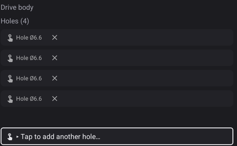
- Open 2D → Bore and pick the four cylindrical mounting-hole faces. Collapse the drawer with its handle if it covers a hole, then reopen it to inspect the selections.
- Confirm Holes (4) and four Ø6.6 entries. Remove an incorrect chip individually.
- Select the 6 mm tool.
- Set Top to Stock top, offset 0 mm, and Bottom to Model bottom, offset −0.2 mm.
- Choose Create Bore.
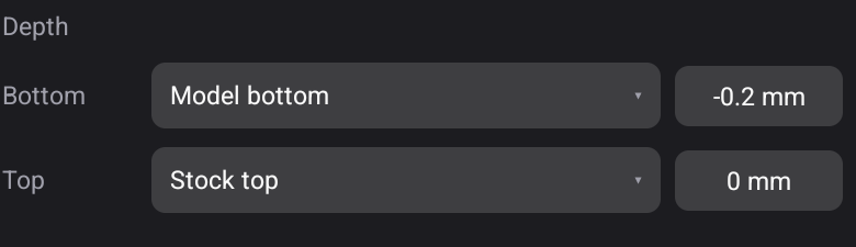
The extra 0.2 mm provides breakthrough into a sacrificial surface. It must not cut into a fixture or machine table in a real setup.
Bore the centre hole
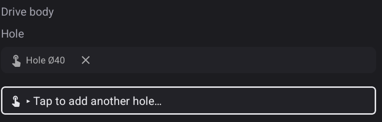
Create a second Bore operation. Pick the Ø40 cylindrical through-bore face and check the drawer says Ø40. The shallow counterbore wall is Ø56 and is not the intended selection. Use the same tool and the same top and bottom references as the mounting-hole operation, then choose Create Bore.
Cut the outside contour with tabs
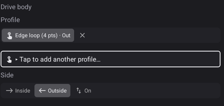
- Open 2D → 2D Contour. Pick the plate's bottom outside perimeter so the contour follows the full plate size rather than the inset edge left by the top chamfer. Choose Outside.
- Select the 6 mm tool.
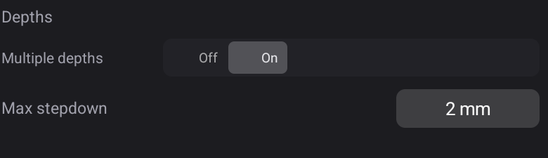
- Under Passes → Depths, turn Multiple depths on and set Max stepdown to 2 mm.
- Under Heights → Depth, set Top to Stock top, offset 0 mm, and Bottom to Model bottom, offset −0.2 mm.
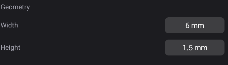
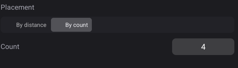
- Turn Holding tabs on. Under the tab Geometry, set Width to 6 mm and Height to 1.5 mm. Under Placement, choose By count and set Count to 4.
- Inspect the preview, then choose Create Contour.
Tabs leave bridges between the part and the surrounding stock. They help retain the part during this last operation; they do not replace clamping, and they must be removed after machining.
These six operations use a flat cutter. They leave the modeled 1 mm top chamfer for a separate chamfering or deburring operation; the outside contour does not cut that bevel.
10 · Simulate the whole tool run
- Open Modify → Simulate and choose All toolpaths.
- Play the simulation. Check the facing coverage, recess boundary, each hole, and the outside contour. Use the position slider to inspect a particular stage.
- Open Stats and inspect Collisions. Resolve any reported collision before posting.
- Check the displayed machining time and distances for unexpected changes.
The illustrated six-operation setup reports 111,799 moves, 20:37, and Collisions: None. The estimate can change with your tool settings and selected geometry.
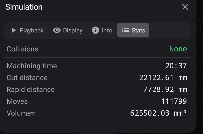
A clean collision check concerns the simulated paths. It does not prove physical workholding, chip clearance or the fit of a real part. Inspect the material left by the complete sequence too.
After a geometry change, open each affected operation with Edit, review its selections and height references, and choose Modify. Repeat the complete simulation before exporting again. See Simulation for playback and display controls.
11 · Post to Projects
Open Export, name the project Fixture plate, and check all six operations under Plate Top. Choose Export. In Projects, open Fixture plate and verify the six files: Face 1.nc, Pocket 1.nc, Pocket 2.nc, Bore 1.nc, Bore 2.nc, and Contour 1.nc.
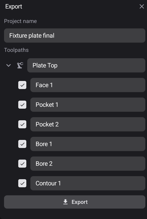
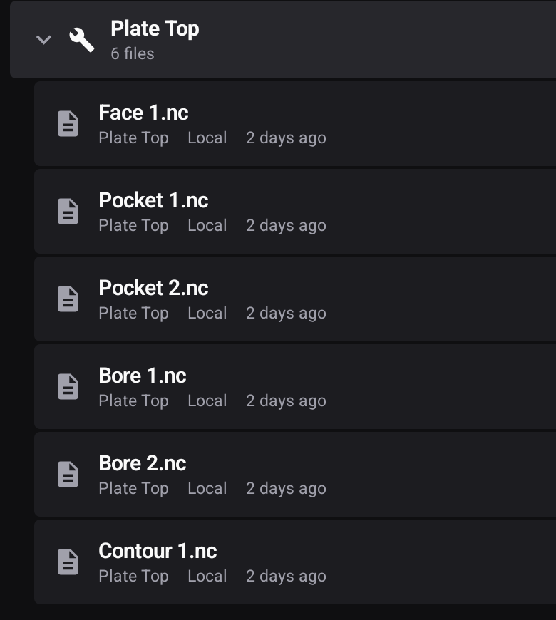
The design remains editable. These files are the posted programs made from that particular set of toolpaths; changing the design does not rewrite a program you already exported. Regenerate, inspect and export again after a model change. Posting covers the handoff in more detail.
12 · Rehearse and cut on your machine
- Secure the blank and connect your controller to the tablet over USB. Check the active machine profile and travel in Connection. Home a machine with homing switches, following the homing gate.
- Fit the correct cutter and set G54 at the stock's top front-left corner, as chosen in Manufacturing. Use probing or the ordinary zeroing controls; verify the work coordinates, tool length and clearance above the stock and clamps. Measure every tool the project calls on this machine.
- Open Fixture plate in Projects and choose Run Project. This loads the files onto Control; loading does not move the machine. Read the first filename, tool and Safety result.
- With the area clear, open Run in the left rail and choose Outline. Watch the spindle-off footprint trace at safe Z and its return. Check the stock edges and clamps.
- Choose Run → Air Run, verify its clearance and spindle suppression, then choose Run → Start Project to rehearse every move. Watch the whole sequence. Choose Run → Air Run again to switch it off after the rehearsal and recheck zero and the cutter before the cut.
- Choose Run → Start Project for the cut. If Work Zero Not Set appears, use Go Set Zero and complete that step before starting again. At Tool Change — T1, follow the safe tool-change procedure, check the named 6 mm cutter is secured and measured, then choose Tool Changed — Continue.
- At File Complete — Tool Change, read the completed and next filenames. Choose Continue only when ready for the next file, and check its separate tool-change prompt. Stop Here ends the sequence at that file boundary; use the running controls to stop an active file.
- Check the six new Completed entries and their line counts in History after the cut.
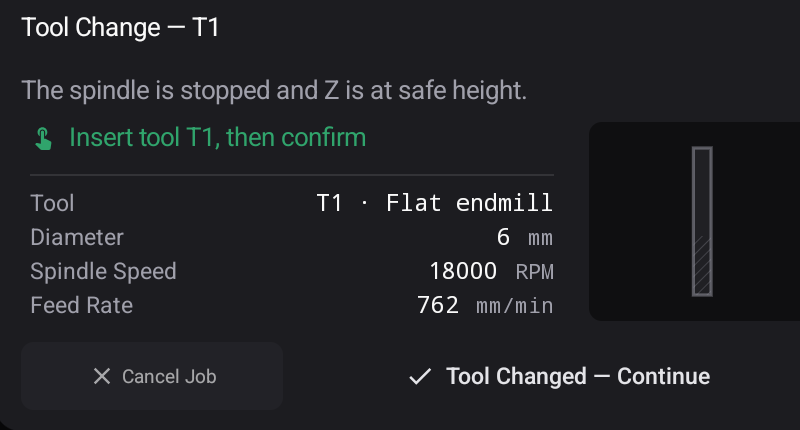
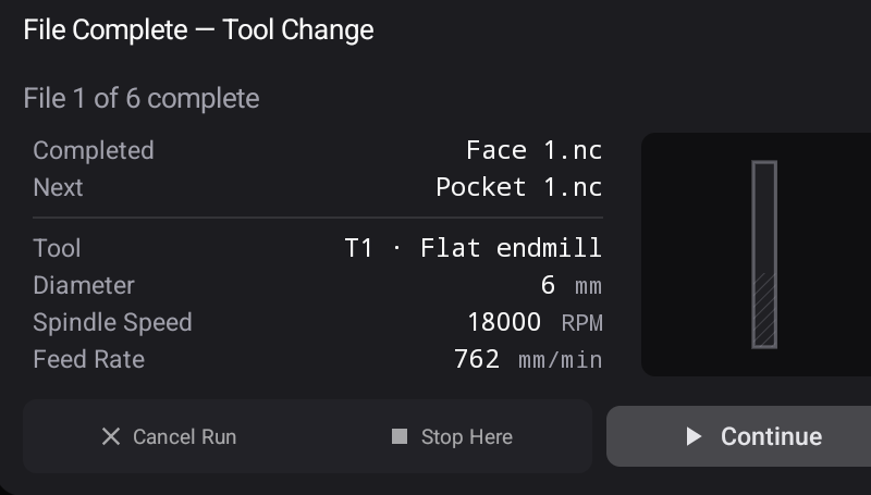

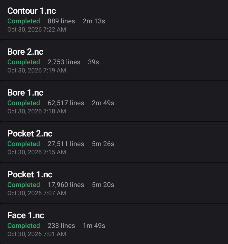
The pictures illustrate the prompts and example completion records. They do not prove that your stock is held or that your tool and cutting settings suit it. Keep watching your machine; use The Control screen, Project runs and Tool changes for the running controls and safe changes.
Keep the design in Showcases so you can return to it when comparing a later edit.