 PRIME MOTION
Analyzing a design
Every tool under Analyze reads the model and tells you something about it. None of them changes your design — you can run any of them at any time, on anything, without consequence.
They live in one family on the rail. Long-press Analyze to reach the rest.
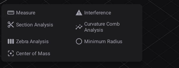
| Tool | The question it answers |
|---|---|
| Measure | How big is this, where is it, and how far or how angled from that? |
| Interference | Do any of these bodies overlap each other? |
| Section Analysis | What does the inside look like? |
| Curvature Comb | Does this edge bend smoothly, or does it kink? |
| Zebra | Do these surfaces really flow into one another? |
| Minimum Radius | Can my cutter reach into every inside corner? |
| Centre of Mass | Where does this balance? |
Each one shows you what it has selected as a row of chips. Tap a chip's ✕ to drop that selection, or tap the same thing again on the model. Clear takes everything off.
Measure
Select one thing and it tells you about that thing. A face reports its area, where its centre sits and which way it faces; an edge reports its length and both ends; a corner reports its position.
Select a second and you get the relationship between them: a distance, the three axis gaps ΔX / ΔY / ΔZ, and — when both are faces — the angle.
The distance row tells you which distance it is, because the two are not the same number:
- Min distance, when an edge is involved — the true shortest gap, so two edges that pass near each other give you the clearance you actually care about.
- Centre distance, when both picks are faces — the gap between the two face centres. Two faces that meet at a corner are touching, so their shortest gap is zero and would tell you nothing; the distance between their centres is the number that means something.
The angle is the angle between the faces themselves, so two parallel walls read 0°, whichever way they happen to face, and a square step reads 90°.
Precision sets how many decimals every row shows. Secondary units adds the same measurement in inches beside the millimetres. Both only change the display — the measurement itself is kept at full precision, so you can turn the decimals down for a quick read and back up again without losing anything.
Interference
Select two or more bodies and press Compute. Any pair that shares space is listed by name with how much volume they share, and those bodies light up on the model.
Include coincident faces decides whether bodies that merely touch count. Off — the normal setting — two parts sitting flush against each other are not interfering. On, they are.
Section Analysis
Select a plane — a construction plane, one of the origin planes, or any flat face — and the view is cut open along it so you can see inside. Everything visible is cut, not just the body you picked from, which is the point: you are looking at the design, not at one part of it.
Distance slides the cut along. Angle 1 and Angle 2 tilt it. Flip swaps which half you keep. Cut colour decides whether each cut face is tinted from its own body's colour — useful when several parts are cut at once and you need to tell them apart — or all the same.
Where the plane passes through material, the cut is filled in, so a solid part reads as solid and a hollow one reads as a wall with space behind it. That fill is the real cross-section, which is why a tube cuts as a ring and a pocket cuts as the shape of the pocket. It is hatched so material is unmistakable at a glance; turn that off with Show hatch if it gets in the way.
Nothing about your model changes. Close the tool and the design is whole again.
Curvature Comb
Select one or more edges. Each grows a comb of spikes: the spike points toward the centre of the bend, and the longer it is, the tighter the bend at that spot. The tips are joined into a curve of their own, and that curve is the thing to read — where it steps or kinks, the edge does too.
Density is how many spikes. Scale is how long they are; wind it up until the shape is easy to read, since only the relative lengths mean anything.
The tightest radius found is reported with it.
Zebra
Select one or more bodies. They are painted with black and white stripes, as though a striped ceiling were reflected in a polished surface — because that is exactly what is being drawn.
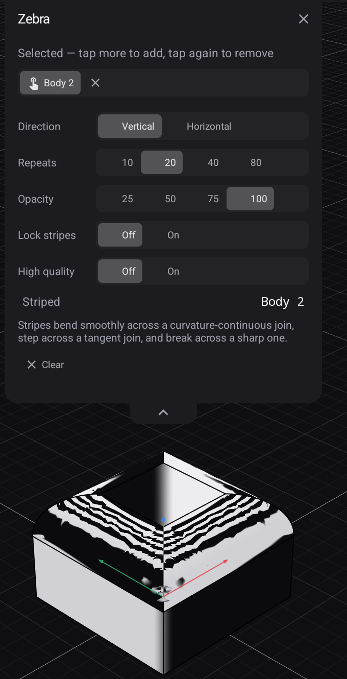
That makes it a continuity test:
- stripes that flow smoothly across a join — the surfaces are curvature-continuous;
- stripes that step sideways — the surfaces meet and share a direction, but the curvature jumps;
- stripes that break — a sharp edge.
Repeats sets how many stripes. Opacity fades them so the part shows through. Lock stripes pins the pattern to the model, so it stops sliding as you orbit — useful for comparing two views; leave it off while hunting, because a moving stripe is what makes a flaw catch your eye. High quality sharpens the stripe edges.
The stripes stay on while you keep working, so you can adjust a surface and watch them respond. Clear removes them.
Minimum Radius
Select one or more bodies and set the tool radius you intend to cut with. Every inside corner is coloured against it:
- red — tighter than your tool, which cannot reach in there; material will be left behind;
- amber — it fits, with nothing to spare;
- green — comfortable.
The tightest radius on the selection is reported, along with the largest cutter that will actually fit it. Outside corners are not coloured — a cutter never struggles to reach around the outside of something.
Ignore below drops corners tighter than a size you name out of the map entirely: past a certain point you were never going to machine that corner, and colouring it red every time is noise. Anything hidden this way is still counted in the panel, so the map never quietly shrinks. Opacity fades the colours over the model.
Sharp edges looks for the case the colours cannot show. The map reads how tightly a face curves, and a corner where two faces simply meet at an angle has no curve to read at all — its radius is zero. Turn this on and those corners are counted, drawn on the model, and the two faces that form each one turn red. The minimum radius then reads 0, and the largest cutter that fits reads none, because that is the truth: no cutter of any size reaches into a square internal corner.
The Sharp corners count appears whenever the setting is on, including when the answer is zero — so "there are none on this part" is something you can actually read, rather than something you have to infer from an absent row.
Centre of Mass
Select one or more bodies. A cross marks where the selection balances, and its position is reported along with the volume and surface area it was worked out from. Several bodies combine, weighted by volume.