 PRIME MOTION
Tutorial: a sculpted handle
A handle can have a narrow end and a fuller middle without being a cylinder. Separate cross-sections let you describe that change directly. A loft joins them; a small curved surface adds a thumb rest where a plain loft would be too smooth to locate your hand.
This example is 120 mm long, with oval ends 22 mm wide and 18 mm high. The middle starts at 30 mm wide, then grows to 34 mm. Manufacturing covers the upper half. The underside, mounting and any remaining workholding material need a second setup.
Start with the fixture plate if design creation, expression entry, cutter selection or setting a work zero is new to you.
1 · Name the design and dimensions
Create Sculpted handle in Showcases. In Parameters, enter these millimetre values:
| Name | Starting value | Purpose |
|---|---|---|
| handle_length | 120 | Distance between the end sections |
| end_width | 22 | Width of each end ellipse |
| mid_width | 30 | Width of the middle ellipse |
| thickness | 18 | Height of the three ellipses |
The handle runs along X. Each oval section lies on a plane perpendicular to X, so its width is along Y and its height along Z.
2 · Make two more section planes
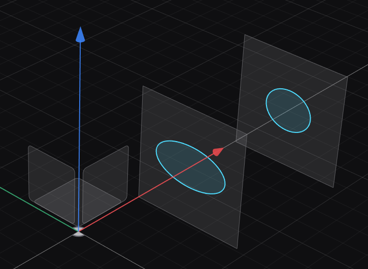
Use YZ Right for the first section. With the Plane family, make an offset plane from it at 60 mm, then another at 120 mm. These are the middle and far-end section planes.
The offset is a distance entered in the plane drawer. If you later change the handle length, update these two distances as well: the middle belongs halfway along, and the far end belongs at the full length. Naming a parameter does not by itself connect every distance to it.
Keep Plane visible while making the sketches. Orbit the view if the planes overlap on screen; select the actual plane you mean, rather than whichever outline is easiest to tap.
3 · Draw three oval sections
Start a sketch on YZ Right. Select Ellipse and draw the first oval around the plane origin. Finish the gesture, switch to Select, and select the ellipse to expose its size readouts.
An ellipse has two semi-axes: half the width and half the height. Enter:
| Section | X position | Semi-axis along Y | Semi-axis along Z |
|---|---|---|---|
| First end | 0 mm | end_width/2 = 11 mm | thickness/2 = 9 mm |
| Middle | 60 mm | mid_width/2 = 15 mm | thickness/2 = 9 mm |
| Far end | 120 mm | end_width/2 = 11 mm | thickness/2 = 9 mm |
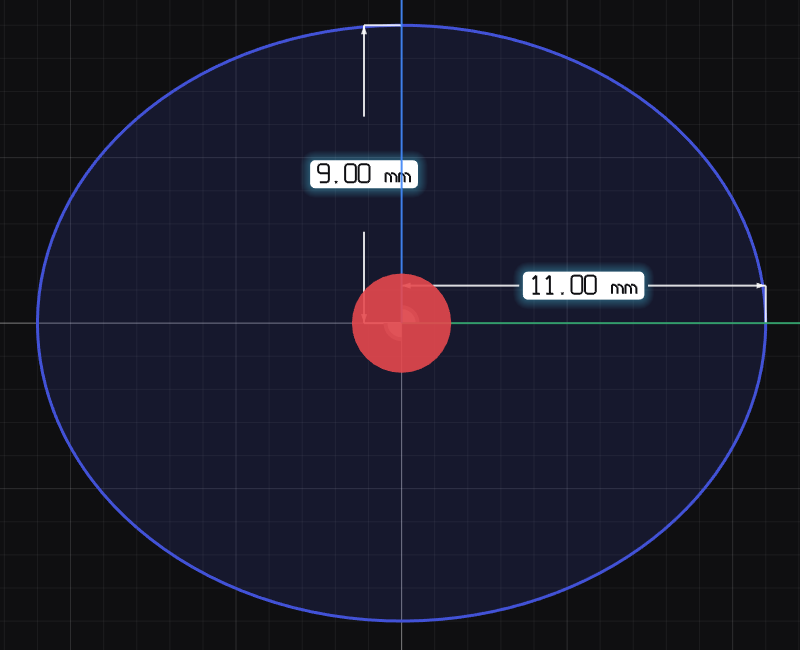
Use the ellipse's own readouts for these values. The line-length Dimension tool is a different control. Finish each sketch, start the next on its own plane, and size that ellipse before moving on.
Centre the three profiles on the same handle axis. Inspect from Front and Top as well as isometric: a small offset can be hidden in a perspective view. Move/Copy can correct a misplaced profile within its sketch. Keep Copy off when moving the original.
These size readouts accept an expression as a value when you apply it. After changing a named width, re-enter its expression in the affected ellipse readout to resize that profile. Do not expect a previously entered semi-axis value to change just because the parameter changed.
4 · Loft through the sections in order
Choose Create → Loft. With Sketch visible, select the first filled oval, choose Add profile, select the middle, then add the far end. Check that the three profile chips are in 0 → 60 → 120 order.
Use Solid, an open sequence, Connected at the start and end, and New Body. No rail or centreline is needed for this example. Apply Loft.
Hide the sketches and planes to inspect the shaded body. It should have two closed end faces and a continuous side that widens towards the middle. A set of oval outlines is not the solid result.
For a width variation, change mid_width from 30 to 34. Edit the middle sketch, select its ellipse, and reapply mid_width/2 to the Y semi-axis: it becomes 17 mm. Keep the Z semi-axis at 9 mm. Finish the sketch and inspect the rebuilt loft.
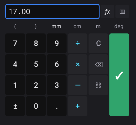
Close and reopen the design. Check the saved section planes and their filled profiles, then show the body again and inspect the shaded loft. Use the viewport Body chip to see the profiles through the solid while checking.
5 · Draw an open thumb-rest curve
Make another sketch on XZ Front, through the handle's middle. Draw an open Fit Point Spline from approximately X35/Z5, through X60/Z10, to X85/Z5. The three points describe a low arch; they are fit points on the curve, not three control-polygon corners.
With the S Pen, keep contact as you draw. Press deliberately at the middle point to add it, then continue to the end and lift. The click confirms an inserted point. A stroke with only its start and end becomes a line, so inspect the arch before finishing the sketch.
Keep the curve open. It will become a surface strip, not a closed profile for an ordinary solid extrusion.
6 · Extrude a surface across the handle
Long-press Design and choose Surface Modeling. Hide the loft body if it obscures the curve, choose Create → Extrude, and select the open spline itself.
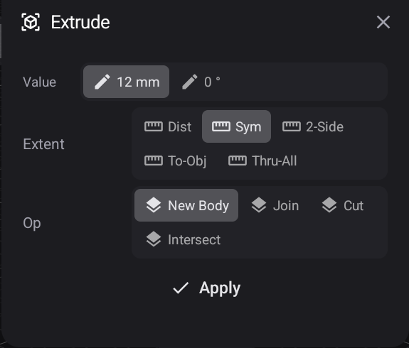
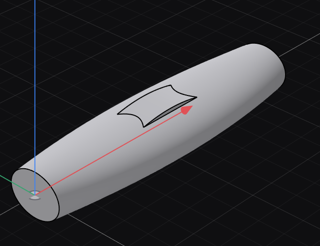
Enter 12 mm, choose Sym, leave the taper at 0°, and use New Body. Apply the extrusion. Orbit the result: it is a curved sheet across the handle. It has area, but no thickness yet.
7 · Give the sheet thickness and join it
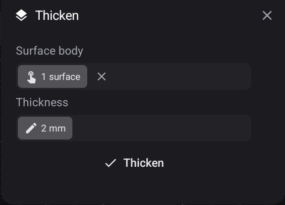
Choose Create → Thicken and select the surface body. If it is hidden inside the loft, temporarily hide the loft with its own eye in the Bodies tree. Select the exposed sheet, use 2 mm, and check the direction shown by the arrow before applying Thicken.
The thickness must put material into the handle as well as forming the raised rest. Two separate solids that merely look close in one view are not a joined handle.
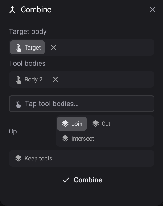
Return to Solid Modeling and choose Combine. Pick the loft as Target body, then the thickened rest as Tool bodies. Use Join and leave Keep tools off. Temporarily hiding the loft can make the tool-body pick clear; show it again before applying the join.
Inspect the resulting rest from several angles. Close and reopen the design, check the shaded body and History, then try Undo and Redo on the join. Undo should separate the two solids; Redo should restore the united handle.

Close and reopen while the join is undone, then choose Redo. Close and reopen once more to check the restored handle before making toolpaths.
8 · Inspect curvature and access
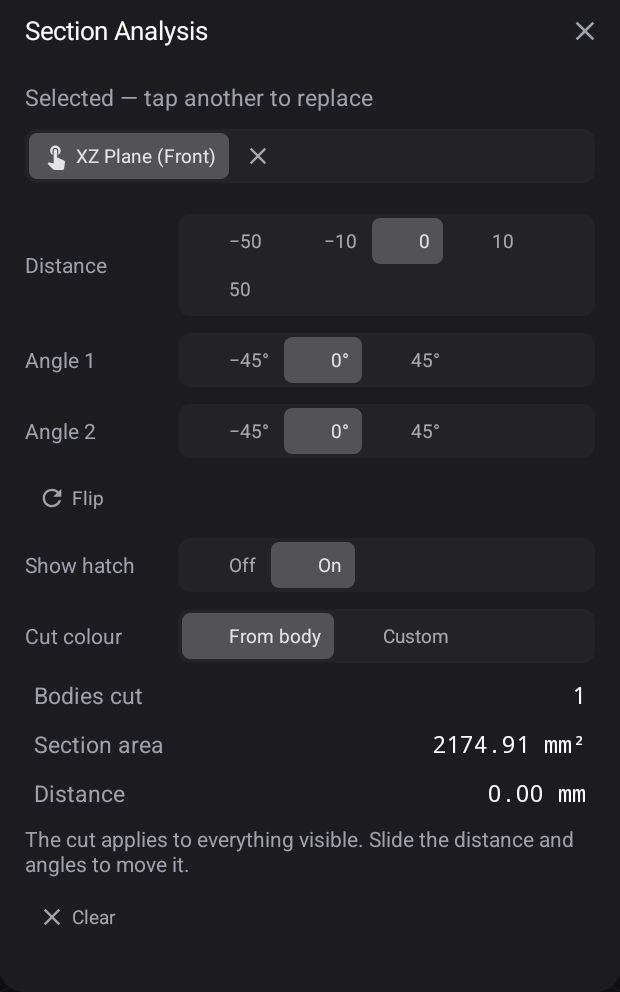
Use Analyze → Section Analysis on XZ Front with zero offset and hatch enabled. It shows the cross-section through the handle and thumb rest. Hide the body briefly if it blocks the plane pick, then show the body again to inspect the cut.
If the plane is hidden, expand Origin in the tree and turn XZ on. Turn the viewport's Plane chip on, hide Body, and pick the small XZ plane near the handle's first end. Check XZ Plane (Front) in the drawer before showing Body again. Turn Plane off to remove the construction-plane rectangles from the view. Keep both angles at 0°, Distance 0, and Show hatch On. This example reports 1 body and 2,174.91 mm² at that section.
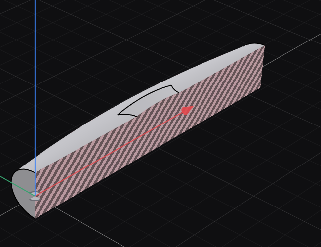
Curvature Comb on a curved edge helps show where curvature tightens. Zebra Analysis makes changes in the visible surface flow easier to see as you orbit. Neither a striped display nor a smooth-looking silhouette alone proves that every face can be machined with your cutter.
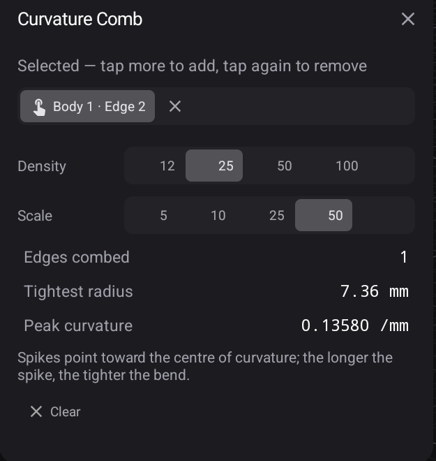
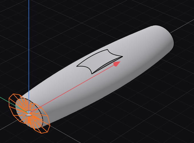
For a clear comb example, pick the elliptical rim at the first end of the handle. Check that the drawer names that curved edge; a straight edge correctly gives no comb. Set Density 25 and Scale 50 to make the teeth easy to see. The end ellipse in this example reports Tightest radius 7.36 mm and Peak curvature 0.13580 /mm. Density and Scale change the display, not the shape of the edge.
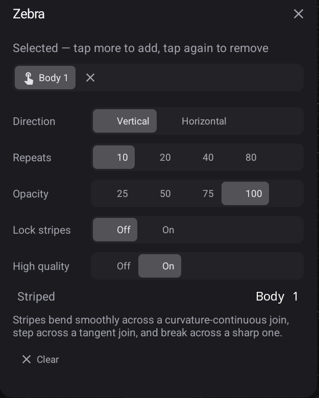
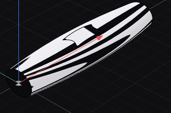
In Zebra Analysis, pick the joined body and use Vertical, 10 repeats, Opacity 100, Lock stripes Off and High quality On for the view below. Orbit to inspect the surface around the thumb rest. A break in the reflected stripes draws attention to a crease; it does not by itself measure the size of that crease.
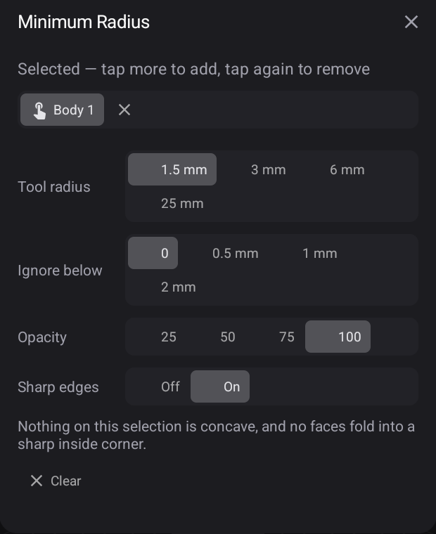
Use Minimum Radius with the finishing cutter's radius as another access check. Inspect the actual regions it reports and consider the shaft, holder and workholding separately. See Analysis.
For the 3 mm ball-nose finishing cutter, choose Tool radius 1.5 mm, Ignore below 0 and Sharp edges On. On this body the drawer reports no concave faces or sharp inside corners. That result concerns inside curvature; it does not check the cutter's reach, holder or clamps.
9 · Rough and finish the upper half
In Manufacturing, create Handle Top with the united handle as the model. Use a Relative Box, 2 mm side offset, 1 mm top offset and 0 mm bottom offset. Pick Stock Box → Top Front-Left corner for the G54 origin. Confirm the stock follows the final thumb-rest geometry.
This setup machines the upper half. Set the bottom limit at the handle's centre plane, rather than sending the cutter around the underside from above. With the end sections centred on Z0 and their 9 mm Z semi-axis, Model bottom +9 mm is that centre plane.
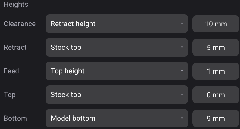
Create 3D Adaptive Clearing with the Amana 45213, a 6 mm flat cutter. For this example, use a 3 mm max stepdown, 1.5 mm fine stepdown, 2.4 mm optimal load and 0.5 mm radial and axial stock to leave. Use Stock top for the top and Model bottom +9 mm for the bottom. Inspect the entries as well as the cutting passes.
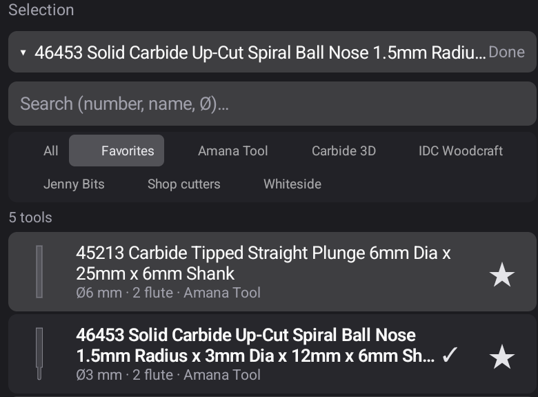
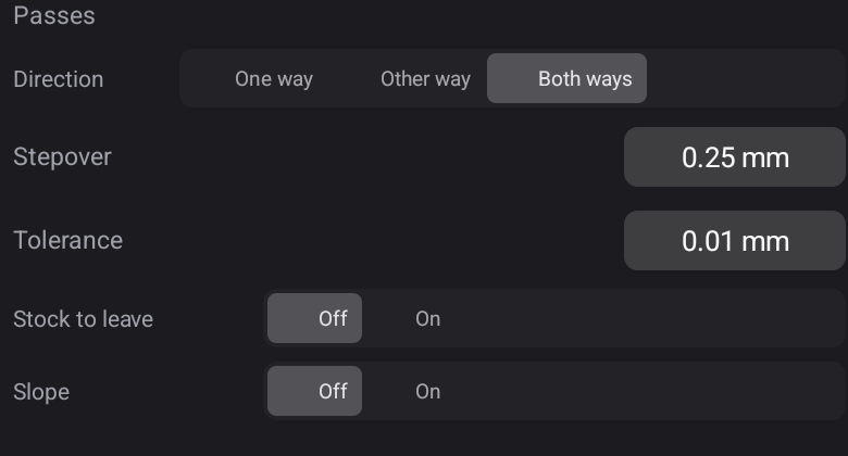
Follow it with Parallel, using Amana 46453, a 3 mm ball-nose cutter. Use Both ways, a 0.25 mm displayed stepover, 0.01 mm tolerance, no stock to leave, no boundary, and the same bottom limit. Smaller stepovers reduce the spacing between finishing passes but increase travel.
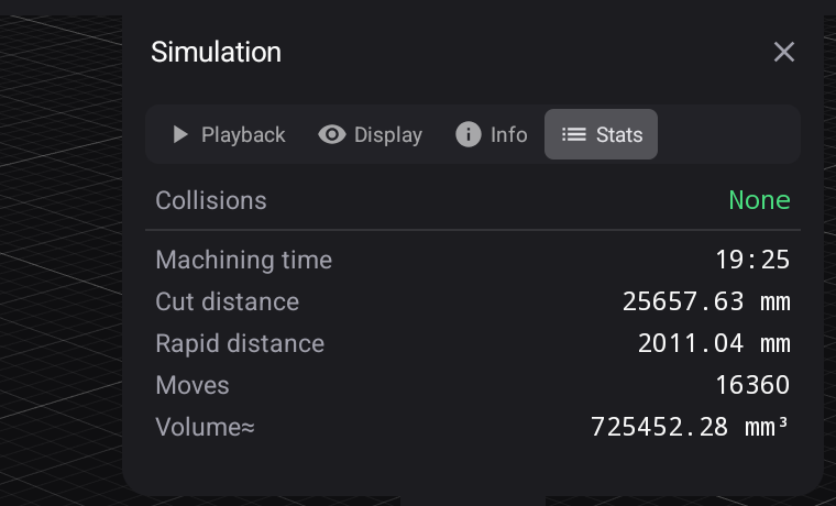
After any model edit, regenerate both operations. In Simulate, choose All toolpaths so the ball-nose pass starts after roughing rather than against a full blank. Inspect the thumb rest, side walls and remaining material. Check Stats → Collisions before posting. For this final setup, All toolpaths reports 16,180 moves, 19:20 estimated machining time and Collisions None.
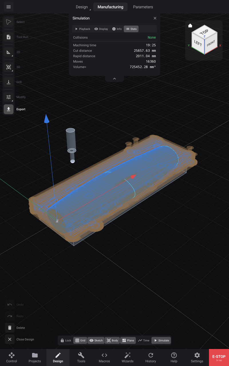
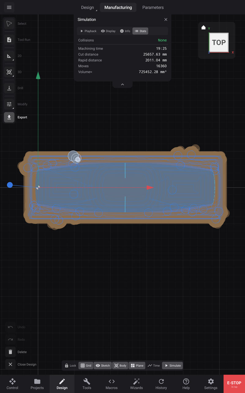
At the end of playback, hide the model with the viewport's Body chip and leave simulated Stock visible. Turn Rapids and Leads off in the simulation display and inspect from isometric and Top. Keep the body's own tree eye on: changing which bodies belong to the setup can change its stock envelope. The blue cutting paths remain over the stock in these views; use them to inspect coverage, then inspect the shaded model separately for the thumb-rest shape. These overview images do not measure surface finish or exact removed volume.
Show Body, Grid, Sketch and Plane again when finished inspecting.
10 · Post and run the checked setup
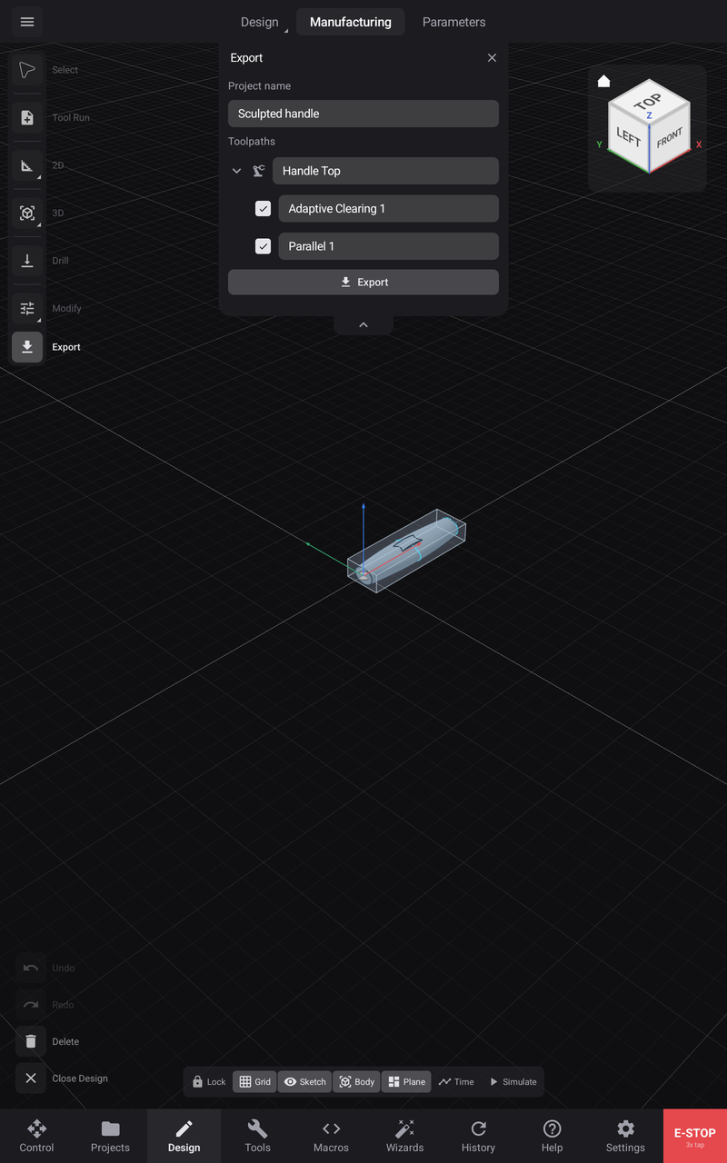
Open Export, name the project Sculpted handle, and select only the checked roughing and finishing operations in Handle Top. In Projects, confirm that roughing comes first and that each file names the intended cutter. In this example the exported files are Adaptive Clearing 1.nc and Parallel 1.nc. Control preprocesses them to 3,115 and 13,085 executable lines respectively; file line counts can include extra comments.

Connect your controller over USB, check its machine profile and travel, and home if homing switches are fitted. Secure the blank with clearance for the cutter and holder. Fit and measure the requested tools, and set G54 at the same stock corner used in Manufacturing. Verify the work zero, tool length and safe clearance before running.
Use Run Project to load the checked files onto Control. Loading does not move the machine. Read the filenames, preview and Safety result. Open Run and explicitly choose Outline for the spindle-off footprint check at safe Z. Choose Run → Air Run, verify its clearance and spindle suppression, then choose Run → Start Project to rehearse the whole job. Choose Run → Air Run again to switch it off, recheck the setup and choose Run → Start Project for the cut. Read each tool-change prompt and check the new completed files in History.
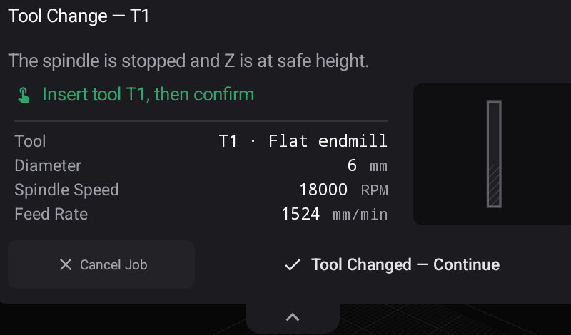
At the first prompt, secure T1, the 6 mm flat endmill, then choose Tool Changed — Continue. Do not confirm before the tool is secured.
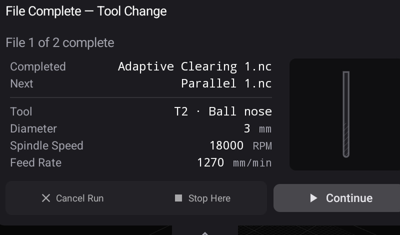
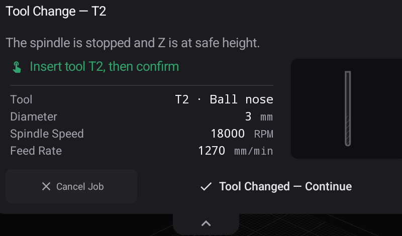
After roughing, the File Complete — Tool Change drawer identifies the completed file and Parallel 1.nc next. Choose Continue, then read the separate secured-tool prompt for T2, the 3 mm ball nose.
The running view keeps the active file, line progress and project queue visible in either orientation. An estimated time can change as the controller executes the programme.
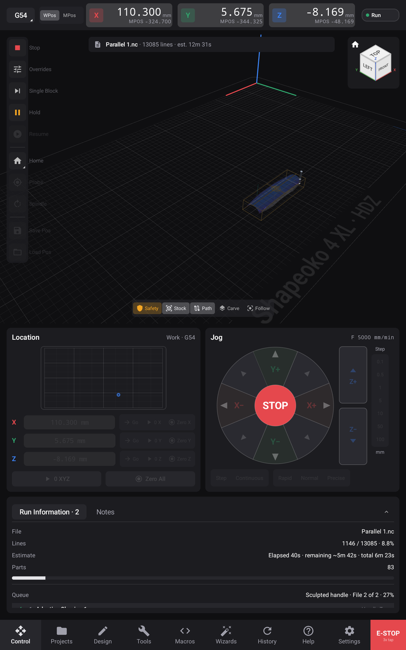
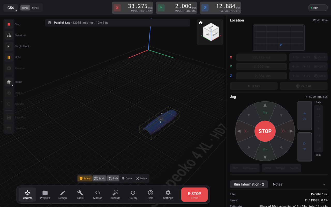
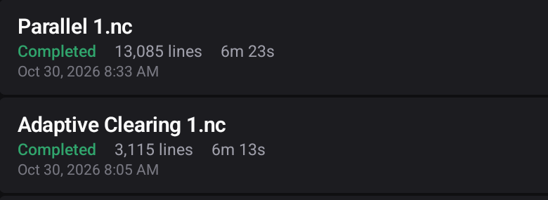
History retains both completed example files. The rougher recorded 3,115 lines in 6m13s; Parallel recorded 13,085 lines in 8m09s. The finishing example used a 200% feed override; begin your own setup at 100% with suitable cutting conditions. These recorded durations include any tool-change wait and are separate from the simulation estimate.

See the fixture plate for the detailed zeroing and file-transition procedure. Keep the finished handle in Showcases together with its section sketches and features.