 PRIME MOTION
Tutorial: a box with machinable joints
A box joint is a relationship between two boards. Start with the boards overlapping at a corner; the joint divides that shared material into complementary fingers. The overlap is intentional at this stage. Two boards that only touch leave no material for the tool to divide.
This example makes four walls around a 160 × 110 mm outside footprint, 70 mm high, from 12 mm stock. It is an open frame: a bottom panel, lid and their attachment need their own design. Keep the assembled model upright for checking the corners, then place the individual boards flat in Manufacturing. These are two views of the same parts, serving different purposes.
Start with the fixture plate if sketch dimensions, parameter expressions, Tool Runs or running a posted program are new to you. See Joinery for the other joint types and their controls.
1 · Give the box shared dimensions
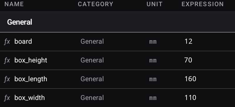
Create Joinery box in Showcases. Add these millimetre values in Parameters:
| Name | Value | Purpose |
|---|---|---|
| box_length | 160 | Overall X length |
| box_width | 110 | Overall Y width |
| box_height | 70 | Height of all four walls |
| board | 12 | Thickness of every board |
Bind the rectangles' dimensions and the extrusions to these names. Typing the same number four times makes four separate decisions; using board in each extrusion gives the walls one shared thickness.
2 · Build the front wall
Start a sketch on XZ Front. Press and drag a 2-Point Rectangle from the plane origin, with its long edge along X and its height along Z. Use Horizontal for the top and bottom and Vertical for the sides where the rectangle did not already acquire those constraints.
Bind its length to box_length and its height to box_height with the expression keypad. Choose Select, then Dimension between edges so the next pick starts a new length measurement. Tapping the already active Dimension tool keeps its first pick; a second edge then asks for an angle. Inspect a true rectangle with a filled interior before choosing Finish Sketch.
In Solid Modeling, choose Extrude, select the filled rectangle and use board, One direction and New Body. The front wall occupies Y0 to Y12. Orbit the result and check the shaded wide face and its thickness. A surface frame around the rectangle is a different result; use Undo, return to Solid Modeling and select the filled profile if you made one by mistake.
3 · Make the other three wall profiles
Use one sketch and one New Body extrusion for each wall. This keeps each board separately selectable for a joint and for its later manufacturing placement.
| Wall | Sketch plane | Rectangle dimensions | Extrude |
|---|---|---|---|
| Front | XZ Front, Y0 | box_length × box_height | +Y by board |
| Back | XZ plane offset to Y98 | box_length × box_height | +Y by board |
| Left | YZ Right, X0 | box_width × box_height | +X by board |
| Right | YZ plane offset to X148 | box_width × box_height | +X by board |
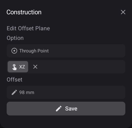
Make the two offset construction planes with the Plane family. The 98 mm back offset is box_width − board; the 148 mm right offset is box_length − board. On this workflow the plane offsets are entered distances. Re-enter them when those dimensions change; the parameter names do not connect an otherwise unbound plane distance automatically.
Size and constrain each rectangle in its own sketch. Keep Sketch and Plane visible while selecting references. Use the tree's eyes to isolate a board or plane when a face obscures the one you need. Check each extrusion's arrow before applying: the table describes the occupied space, not a direction to infer from a perspective view.
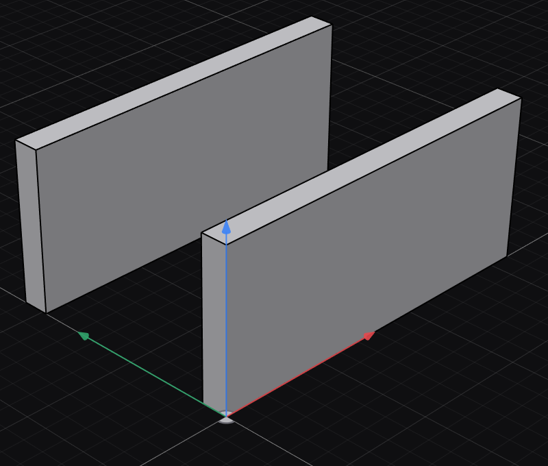
For the left side, sketch on YZ Right, press-drag the rectangle, and bind its width to box_width and height to box_height. The rectangle receives four coincident corners, two horizontal and two vertical constraints. Finish the sketch and extrude its fill by board as a New Body.
For the opposite side, make an Offset plane from YZ at 148 mm. If another plane or a board covers the origin plane, temporarily hide it with the tree eye. Pick the visible YZ plane in the viewport; tapping its name in the tree does not fill the reference slot. Confirm YZ and 148 mm before choosing Create.
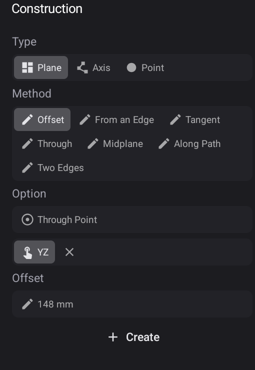
Use the left sketch's ⋮ → Duplicate, then the copy's ⋮ → Redefine Sketch Plane and choose the new plane. This retains its two named dimensions and rectangle constraints. Extrude the copied fill by board, again as a New Body. Restore the visibility you used for picking.
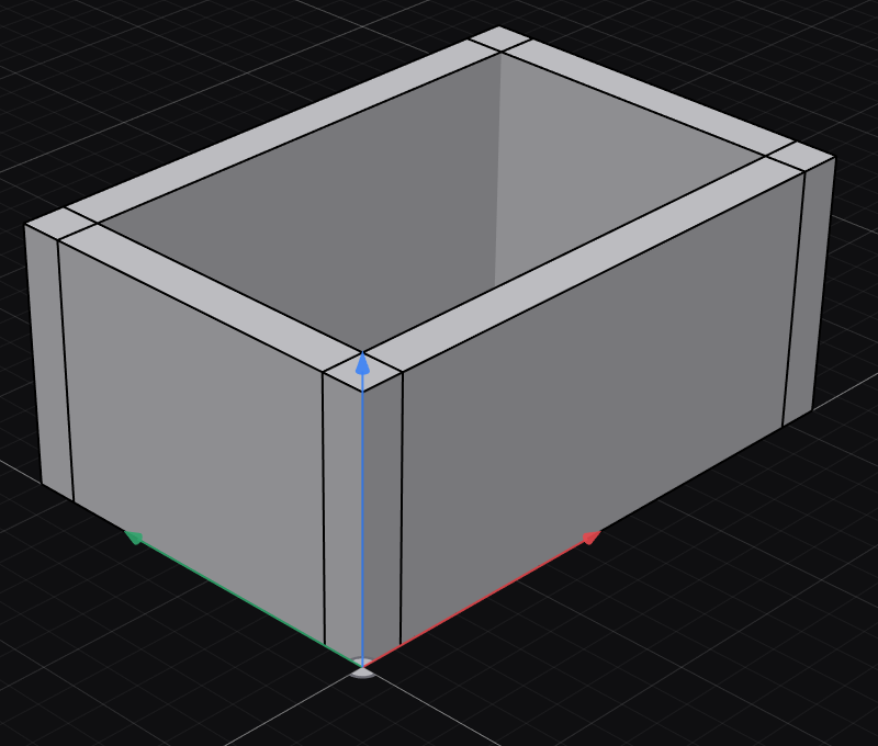
Inspect the four shaded boards from above. Each corner should have a 12 × 12 mm overlap running up the height. Use the tree eyes to identify each board before choosing the Driving bodies.
4 · Divide the four corners into fingers
Long-press Joinery in the Assemble group and choose Machinable Joint. Under Bodies, select all four boards. Open Driving bodies and select the front and back boards from those participants. In this example, those are Body 1 and Body 2; the side boards are Body 3 and Body 4. Opening the selection sheet tells the next tap what to pick; return to Bodies if you need to change the participants.
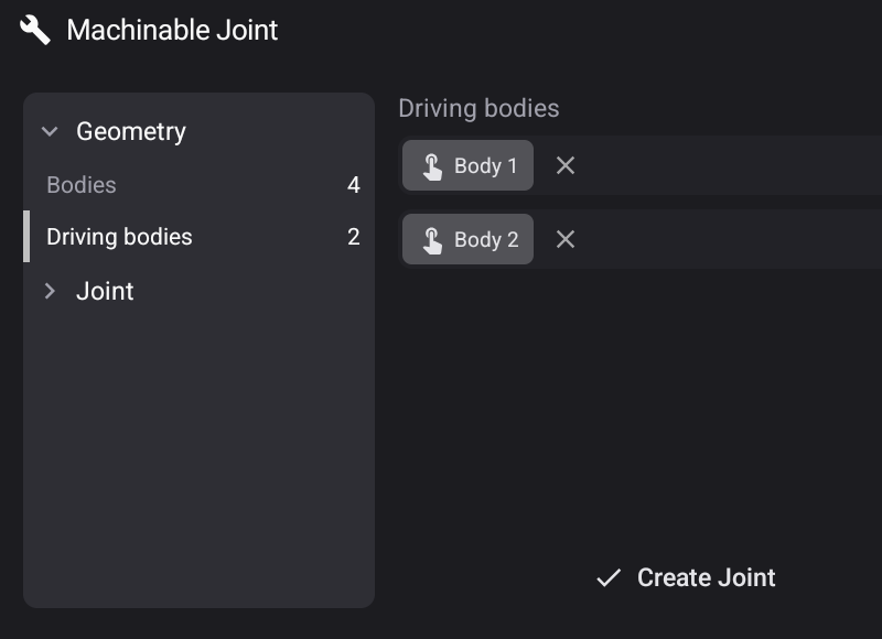
Choose Type → Box joint, then set Count to 5 for this 70 mm high overlap. Under Corner bit, choose 1/4in (6.35 mm) for this example and use Sniglet relief. The relief makes the inside corners accessible to a round cutter; use the same cutter diameter for the machining operation.
Choose Create Joint and wait for Cutting… to finish. Inspect the fingers on both boards. The driving board receives the authored joint shape; the other participant receives its matching cut. This one operation makes the four corners. A result on one board alone is not a complete joint.
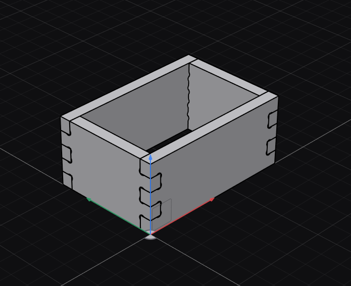
The joint includes its design fit allowance; its drawer has no editable clearance field. Inspect the resulting fit, and keep CAM stock allowances and the model's joint fit as separate decisions. A simulation does not establish the fit of real wood.
5 · Inspect the four corners
Inspect the front, back and inside corners. Keep the front and back boards as the driving pair and the side boards as their mates if you reopen Edit Joint to change its settings.
Use Explode from the Joinery family, select all four jointed boards, and use Viewing gap 25 mm to separate the parts for inspection. Restore returns them to the assembled positions. Explode needs at least two selected boards. It is a viewing operation; it is not the flat machining layout.
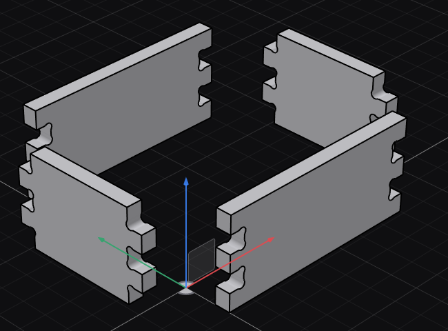
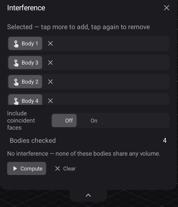
Use Analyze → Interference on all four bodies to inspect their shared volume. Read the result with Include coincident faces in mind: touching faces and overlapping material are different checks. Here, with coincident faces Off, Bodies checked 4 reports No interference.
Use Section Analysis through a corner when the inside contact is hard to see. Select a wide front face, set Distance −10 mm and wait for the result to finish updating. The settled section in this example cuts three bodies, with Section area 11053.82 mm². Close the analysis and wait for the complete shaded box to return before changing the model.
6 · Try 18 mm boards without losing the corners
Keep the outside footprint at 160 × 110 mm while trying thicker stock. The back wall must move to Y92 and the right wall to X142, because 110 − 18 = 92 and 160 − 18 = 142. Changing board alone changes thickness; it does not move sketches whose planes use entered distances. Prepare the wall positions before asking the joint to divide their new overlaps.
Use this sequence before making the machining setup:
- Show Time and find the Box joint feature. Long-press it and choose Suppress. The plain overlapping boards return. Leave the four wall extrusions available.
- Create a new Offset plane from YZ at 142 mm for the right wall.
- Create another Offset plane from XZ at 92 mm for the back wall. Hide bodies or other planes temporarily if they cover the origin plane you need to pick.
- Open the copied back sketch's ⋮ → Redefine Sketch Plane and select the new XZ92 plane.
- Redefine the copied right sketch onto the new YZ142 plane. Check the selected plane in each drawer before confirming; creating a plane by itself does not attach a sketch to it.
- In Parameters, change board 12 → 18. Wait for all four walls to finish rebuilding.
- Return to the timeline and Unsuppress the joint. Wait for the fingers to return, then inspect every corner.
Keep the original XZ98 and YZ148 planes. They are the references for the original 12 mm version, so there is no need to guess their positions when returning to it.
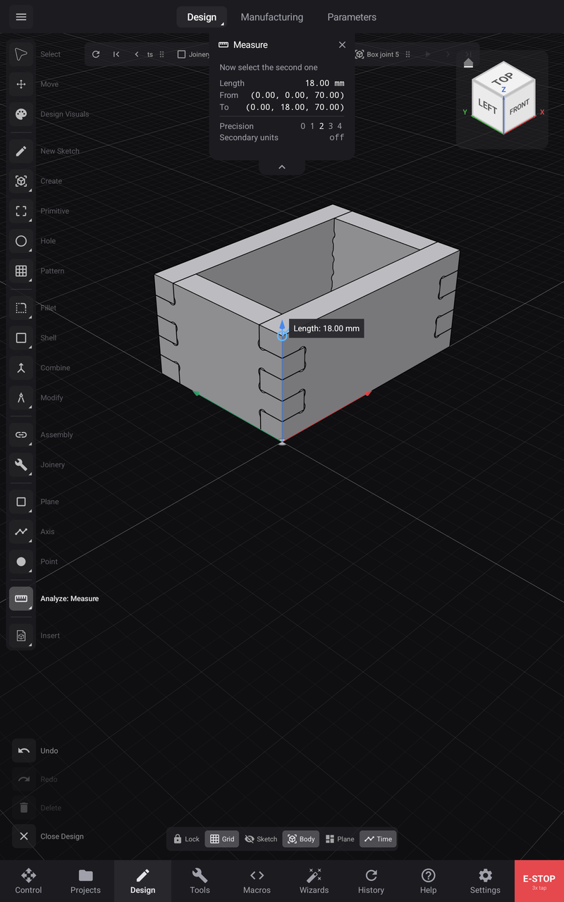
Close and reopen the design normally. Use Analyze → Measure on a short top edge across a wall's thickness. Here it reads 18.00 mm, from (0, 0, 70) to (0, 18, 70). Check the shaded walls and fingers as well as the parameter: the number in the table is only the requested size; the measured solid is the result.
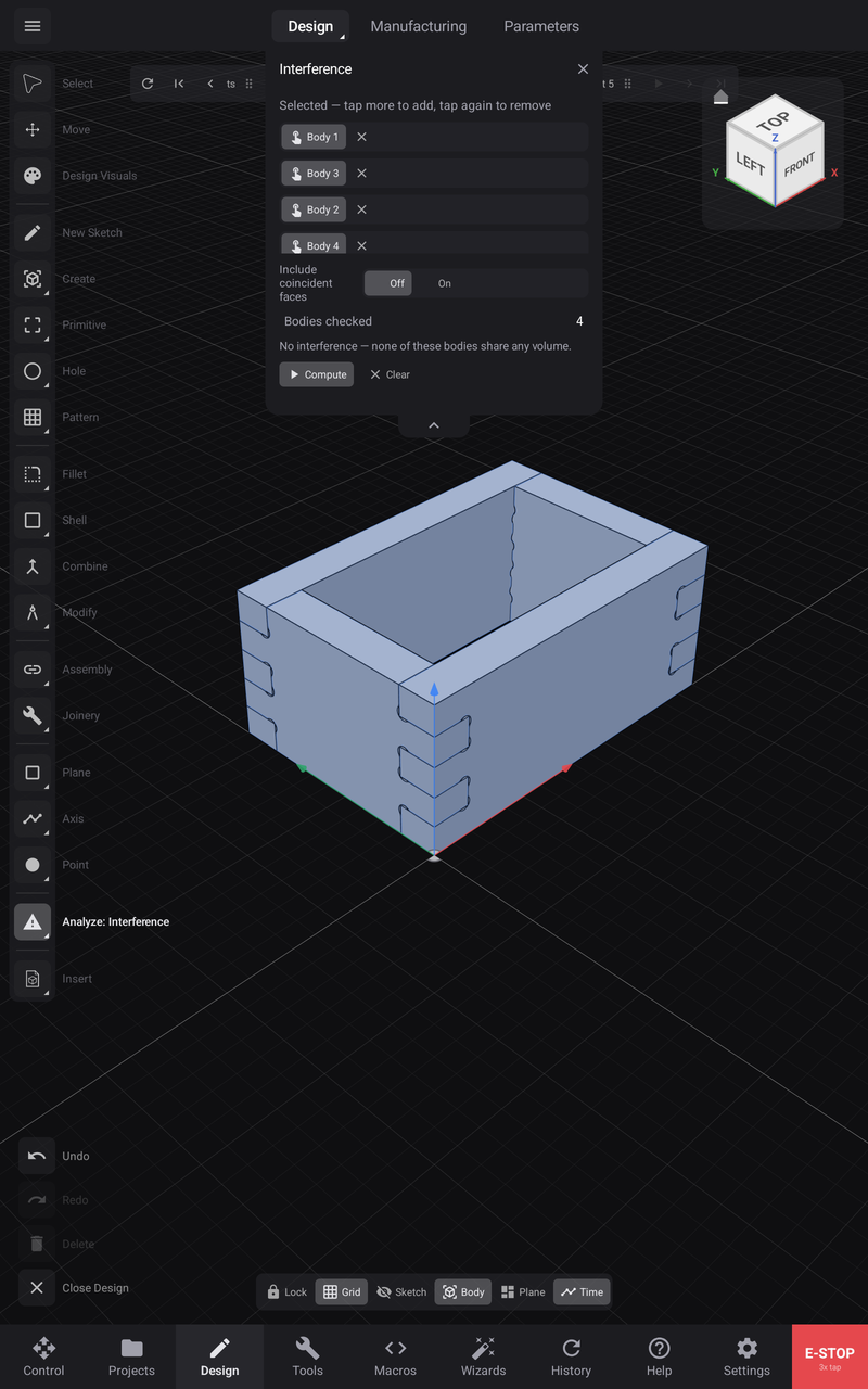
Repeat Analyze → Interference with all four bodies. With Include coincident faces Off, the thicker version reports Bodies checked 4 and No interference. This checks shared volume, not the fit of a real glued joint.
7 · Restore the 12 mm example and check Undo and Redo
Before adding other features, use Undo through the seven changes above. They reverse in this order: unsuppress, thickness, right sketch plane, back sketch plane, the two new planes, then suppress. Wait for each rebuild; the last Undo restores the original joint on 12 mm boards.
Use Redo through the same seven changes and inspect the settled 18 mm fingers again. Then Undo those seven changes once more for the final 12 mm example. Close and reopen normally. Check board 12, the four shaded boards, the corners and the feature timeline before continuing. If you made other edits in between, inspect what each Undo will reverse instead of counting seven blindly. Do this exercise before CAM so Undo does not remove your machining work.
8 · Lay the four boards flat
Switch to Manufacturing and create or edit a Tool Run. Under Geometry → Model & WCS, select all four jointed boards as models. Turn Manufacturing model on to give the boards a flat machining arrangement while retaining their upright design positions.
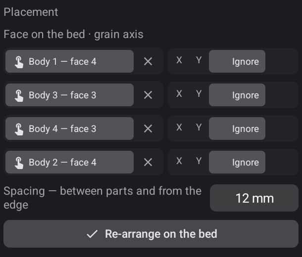
In Placement, choose the wide face of each board that should lie on the bed. This example uses Body 1 — face 4, Body 3 — face 3, Body 4 — face 3 and Body 2 — face 4. Face numbers can differ after other edits; identify the broad face rather than copying a number onto the wrong face. Leave the grain direction at Ignore for this software exercise.
Enter Spacing 12 mm, then choose Re-arrange on the bed. Entering a new spacing is only the request; re-arranging applies it to the placement. Inspect all four boards lying flat, separated from their neighbours. A gap must accommodate the cutter's outside paths and the workholding. The 6.35 mm cutter used below needs more than a 6 mm gap when it cuts between neighbouring parts.
On the Shapeoko 4 XL · HDZ profile, this arrangement is a single row of four boards. Its placed model bounds are approximately 576.506 × 70.031 × 12.031 mm, within that profile's 870 × 440 mm bed. Check your own arrangement after changing the model, spacing or machine; a layout that fits this bed may not fit a smaller one.
9 · Set stock and the program origin
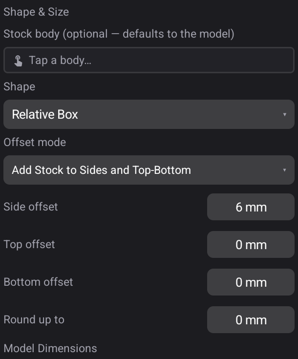
Under Stock → Shape & Size, choose Relative Box and Add Stock to Sides and Top-Bottom. Set Side offset 6 mm, Top offset 0 mm, Bottom offset 0 mm and Round up to 0 mm. This puts a margin around the arranged boards while leaving their top at the stock top.
Return to Model & WCS. Choose Stock Box for the origin and pick the Top Front-Left corner in the viewport. Read that corner name in the drawer before committing. Under Program, name the run Joinery flat and use G54. Confirm Create Tool Run or Modify Tool Run.
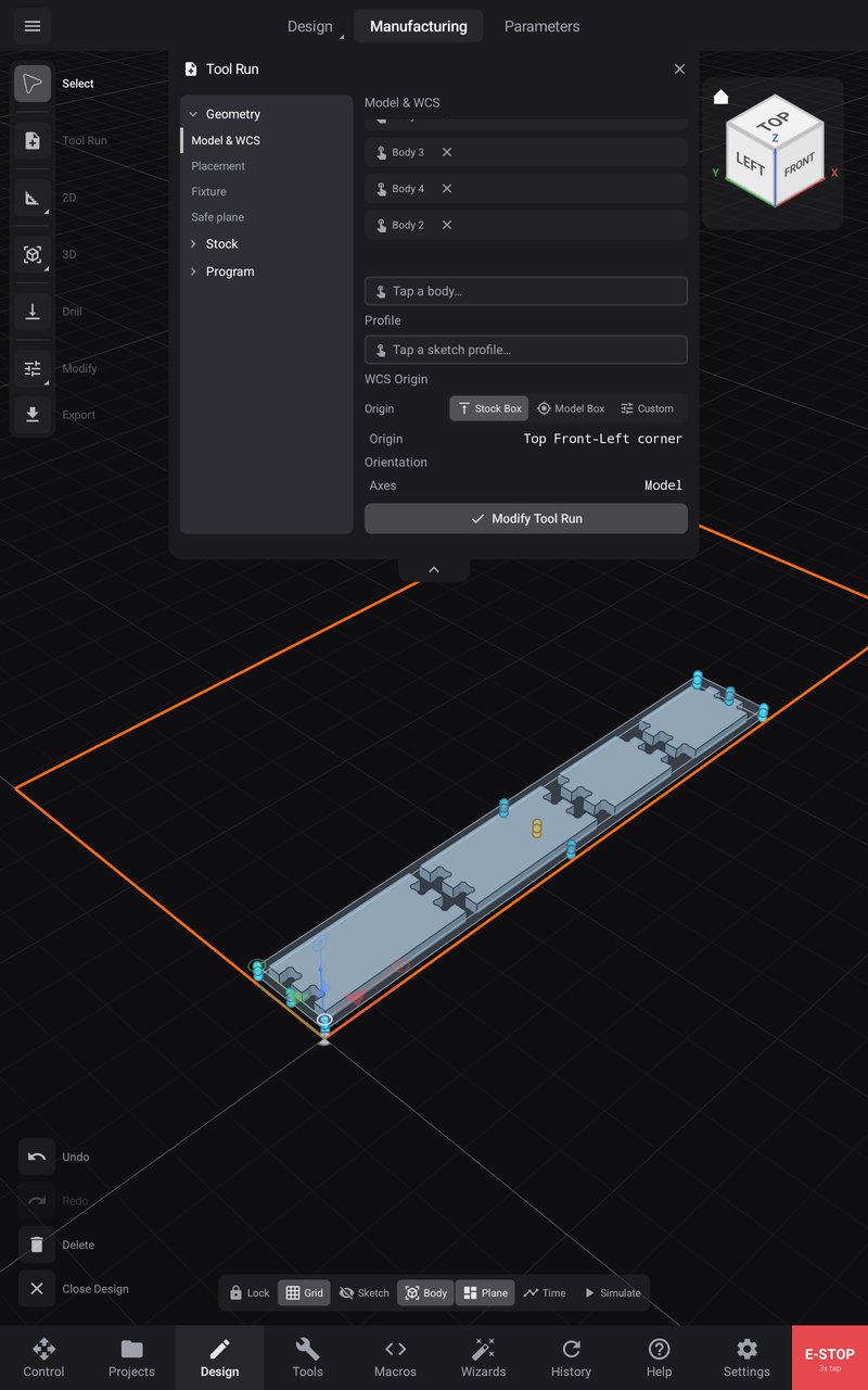
The model's assembled origin and the program's work origin have different jobs. The first keeps the box design understandable; the second is the point you will locate on the stock in Control. See Stock and setups for the other origin choices.
10 · Cut the four outside profiles
Choose 2D → Contour. In Geometry, pick one closed outer edge loop for each flat board. Check four loop selections and set each to Outside. The fingers belong to those outlines; a rectangle around the whole row would cut a different part.
Use these example settings, then choose cutting conditions for your material and machine:
| Section | Setting |
|---|---|
| Tool Library | 1/4 in downcut, flat endmill, 6.35 mm, T1, two flutes |
| Passes → Depths | Multiple depths On, maximum stepdown 2 mm |
| Heights → Depth | Top Stock top, offset 0 mm; bottom Model bottom, offset −0.2 mm |
| Tabs | On, width 6.35 mm, height 1.59 mm |
| Tabs → Placement | By count, 4 per contour |
| Feed & Speed | Spindle 12000 RPM, cutting 1000, plunge 300, lead 500, retract 3000 mm/min |
The extra 0.2 mm reaches below the model bottom, so a real setup needs a sacrificial surface and suitable clearance underneath. Tabs leave bridges that retain the boards after the final pass. Inspect their positions before relying on them; choose stock, feeds and workholding for your actual material and cutter before a physical cut.
Create Contour 1 and wait for its path. Inspect all four outlines, the finger recesses and the space between neighbouring paths. A change to the model, arrangement or stock can make a previous path stale; update it and repeat simulation before posting.
11 · Simulate the complete setup
Open Simulate, choose All toolpaths, play the run and move to its last position. Inspect from Top and an angled view. Use Display → Stock to inspect the remaining stock, and hide the design bodies temporarily if they conceal it. Restore their visibility afterwards.
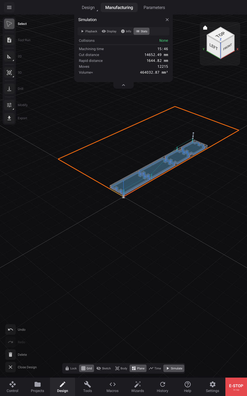
Open Stats and inspect the stock and every finger outline as well as the collision result.
The current example shows four boards lying flat, with Collisions None, 15:46 machining time, 14652.49 mm cutting distance and 12215 moves. Inspect the remaining stock and each finger outline as well as the statistics before posting your own result.
Simulation does not establish glue fit or whether real clamps hold.
12 · Post, rehearse and cut on your machine
Choose Export, keep Joinery flat and Contour 1 selected, and export to the Joinery box project. Open that project in Projects and check the posted file before Run. For this example, Contour 1.nc starts with millimetres, absolute coordinates, G54, T1 M6 and S12000 M3. Its comment identifies Top Front-Left corner of stock as work zero.
The posted stock is 588.506 × 82.031 × 12.031 mm. Its lowest cutting Z is −12.231 mm: the placed model's 12.031 mm height plus the chosen 0.2 mm bottom extension. Use the posted values when checking clearance; do not substitute the nominal board 12 parameter for the final program's bounds.
Proceed only when the current four-board layout and simulation pass the checks above.
Connect your controller over USB, verify its profile and travel, and home if homing switches are fitted. Secure the boards or a suitable blank with clearance for the outside contours and cut-through depth. Fit and measure T1, 6.35 mm. Set G54 at the same stock top front-left corner used in Manufacturing, then verify zero, cutter length and clamp clearance.
Choose Run Project. Loading does not move the machine. Read the filename, preview and Safety result, then open Run and explicitly choose Outline for the spindle-off footprint check at safe Z. Choose Run → Air Run, check its clearance and spindle suppression, then choose Run → Start Project for the rehearsal. Choose Run → Air Run again to switch it off, recheck the setup, and choose Run → Start Project for the cut. Confirm Tool Changed — Continue only after the requested tool is secured and measured.
The completion picture records an earlier run of the posted flat program. It reports 12249 lines in 10m14s and returns to Idle. Feed override was 200% until line 7942 (64.8%), then restored to 100%; rapid and spindle stayed at 100%. Check and simulate your current path before posting it. The line count is the prepared program shown in Control; loading can remove comments, split rapid moves and add a spindle-start dwell, so it can differ from the number of text lines in the exported file.

Return to History. Check Contour 1.nc, Completed, 12,249 lines and the duration in the relevant row. The retained History picture records an earlier run and duration. A simulation result and a posted file are useful checks; this History entry is the record that this example program finished. Your cut needs its own completed record.

Keep Joinery box in Showcases, with its sketches, original construction planes, shared parameters, joint feature and final flat Tool Run available for later edits.