 PRIME MOTION
Tutorial: an import round trip
A file that opens successfully has passed only the first check. A round trip checks what survives when you bring geometry in, send it out again, and bring the exported copy back. Compare that copy with the original at the same size and position before depending on it for another job.
This example uses Gibson SG BODY.step and Gibson SG BODY.stl, two versions of the same guitar body. Keep the source files untouched. Give every export a new name in a separate folder so you can tell an original from a copy you made during this exercise.
STEP carries CAD surfaces and edges. STL carries triangles and does not record its units. A smooth curve can therefore stay smooth in STEP while looking faceted in STL. Neither format carries the sketches, parameter expressions or feature history that created the source part.
See Importing STEP and STL and Exporting bodies for the individual controls.
1 · Create a comparison design
Open Showcases, create a new design and name it Import round trip. Work outside a sketch; STEP and STL insertions add bodies to the design.
Long-press Insert and choose STEP. Choose Keep file position to preserve the coordinates saved in the file, then tap File Asset. In the local file browser, open the SD card's SG folder and choose Gibson SG BODY.step.
Wait for the import to finish. In the tree, check both results:
- Canvases holds the unchanged original.
- Bodies holds the derived body you can select, measure and edit.
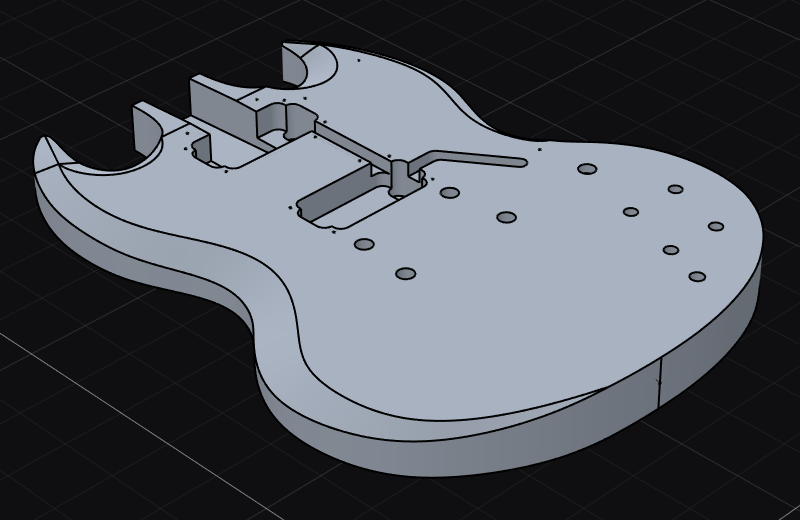
Orbit the body and look for shaded faces, the body outline and the routed openings. An outline alone is not evidence of a solid. Keep this first derived STEP body as your comparison reference.
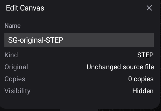
For clear labels, open the STEP asset's ⋮ → Edit under Canvases and name it SG-original-STEP. Press the keyboard's Done to save the name. The asset still says Unchanged source file; naming it does not change the original geometry.
2 · Check placement and dimensions
Use Analyze → Measure to inspect a known straight edge or the distance between two opposite planar faces. Record the selections as well as their values: a width measured between two faces is a different quantity from a diagonal measured between vertices.
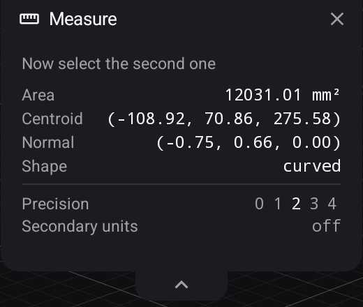
Close Measure with its ✕ to clear its active picks and leave measuring. To start another measurement, choose Analyze → Measure again, then pick the new first face or edge. The drawer shows that first selection and asks for the second one.
Check the body's orientation from Top, Front and an isometric view. Keep file position uses the saved coordinates. Choosing XY Top, XZ Front, YZ Right or a construction plane instead places the imported geometry on that plane; the two choices need not produce the same position.
Use the same placement for every copy in this comparison. Coincident copies can look like a single body, so use each body's eye in the tree to inspect one at a time. A darker overlapping surface is not a measurement of agreement.
3 · Bring in the original STL
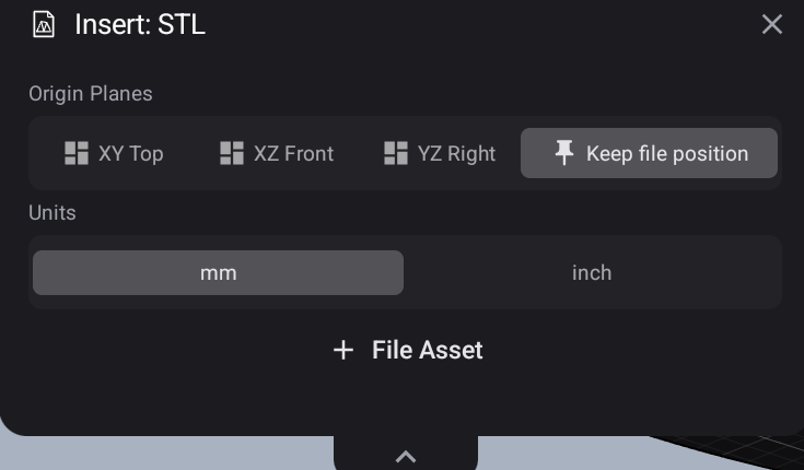
Choose Insert → STL, choose Keep file position, and set Units to mm before File Asset. Choose Gibson SG BODY.stl from the same source folder.
The unit choice is a scale decision: reading millimetres as inches makes every length 25.4 times larger. Check a known size immediately after import. Do not resize a wrongly interpreted mesh by eye and call it a matching copy.
In this example the STEP-derived body is SOLID, and the STL-derived body is Gibson SG BODY. Body names come from the import; they are not a format label. Hide SOLID and inspect the STL-derived body. Curves are made from planar facets; zoom into a curved edge to see the difference. Compare the same measured sizes and openings, then hide the STL body when you return to the exact STEP reference.
Name its Canvas asset SG-original-STL in the same way. These asset names distinguish the sources; the names under Bodies can differ.
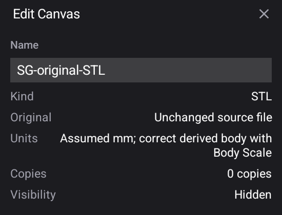
The asset's ⋮ → Edit drawer also shows Kind, Original and Units. Here the STL original remains unchanged, and its Units note says that millimetres were assumed. Check that interpretation against a known size before correcting the derived body's scale.
4 · Export the STL-derived reference as STEP and STL
Use Gibson SG BODY, the body derived from the original STL, for this first round trip. This deliberately checks a common trap: saving a faceted body as STEP does not turn it back into exact curved CAD surfaces. Keep SOLID, the original STEP-derived body, for the later editable copy.
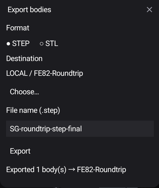
Open Gibson SG BODY → ⋮ → Export…. In Export bodies:
- Choose STEP.
- Choose This device → Internal storage → Download, create or open FE82-Roundtrip, then choose Save here.
- Enter a distinct name, such as SG-roundtrip-step.
- Choose Export and read the saved-file message.
Export that same body again as STL, named SG-roundtrip-mesh, with Medium refinement. The STL export is binary and uses millimetres. A higher refinement describes curves with more triangles and produces a larger file; it does not restore an editable circle to an existing mesh.
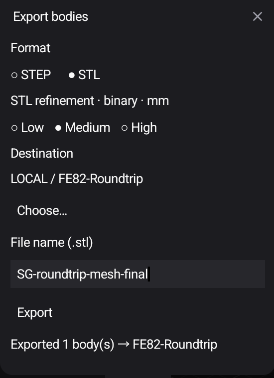
Select one body for this STL export. The STEP choice can carry several selected bodies together; STL is offered for a single selected body.
5 · Re-import the exported copies
Use Insert → STEP → Keep file position → File Asset to open SG-roundtrip-step.step from your chosen export folder. Repeat with Insert → STL, mm, and SG-roundtrip-mesh.stl. These are the files you just exported, not the source files from the SG folder.
The tree now has four Canvas assets: the two originals and the two exports you brought back. The original STEP body is SOLID, the original STL body is Gibson SG BODY, its STEP-format round-trip copy is Gibson SG BODY (2), and the exported mesh is SG-roundtrip-mesh. Check your tree rather than relying on identical-looking overlapping bodies.
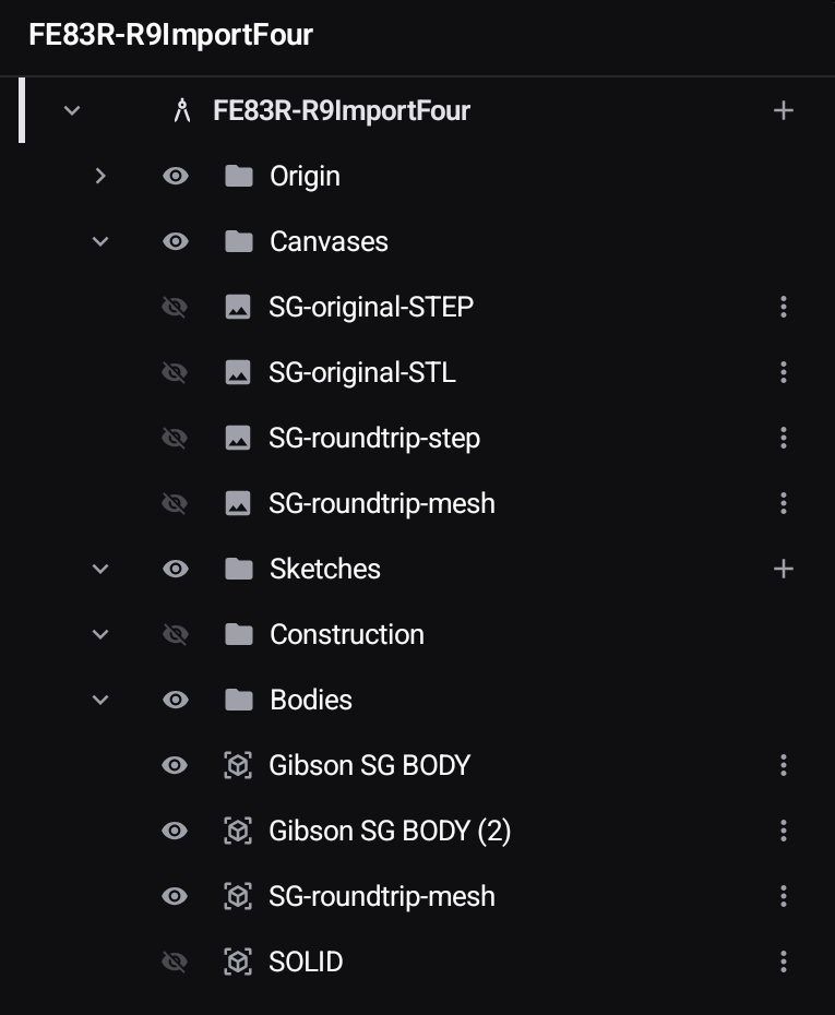
Compare the original STL-derived reference, its STEP-format round-trip body and its STL round-trip body one at a time. Reuse the same measured faces or corresponding edges wherever possible. Check position, overall size, openings and curved surfaces. A matching thumbnail does not establish that a small hole, a shallow recess or the units survived.
For a repeatable first check, select the large flat top face away from the routed openings with Analyze → Measure. In this example, the original STL-derived face reads 78,523.42 mm², the round-trip STEP face 78,523.38 mm², and the round-trip STL face 78,523.43 mm². All three display centroid (7.29, 84.78, 293.04) and normal (0, 0, 1) at two decimal places. Small differences in a displayed area do not establish the accuracy of every edge. Continue with known lengths, openings and the curved outline before accepting a copy for a job.
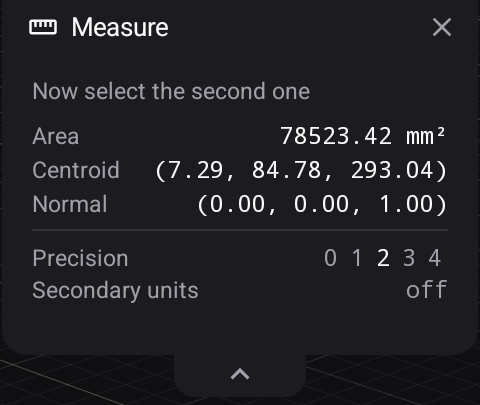
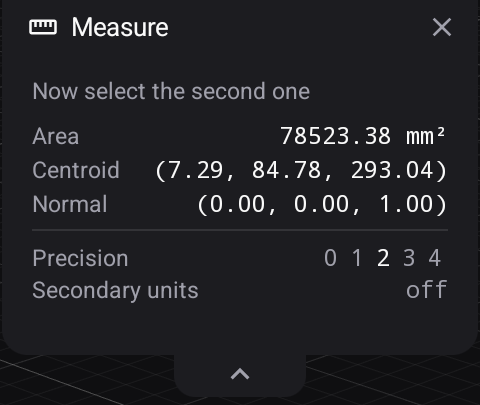
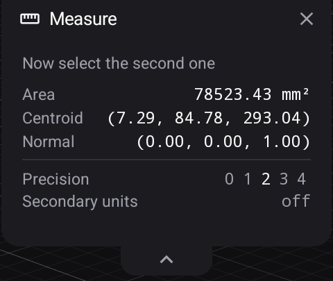
Both exports started from the STL-derived reference, so both retain faceted geometry. The STEP file does not restore the exact curves that were lost when the source mesh was made. The STL copy's tessellation also depends on the chosen refinement. The source app's feature history does not appear in either imported body.
6 · Repeat from the exact STEP reference
Now repeat the export and re-import using SOLID, the body derived from the original STEP. Hide the other bodies, then open SOLID → ⋮ → Export…. Save SG-exact-step as STEP and SG-exact-mesh as a Medium, binary, millimetre STL in the same separate folder.
Bring both exports back with Keep file position, choosing mm for STL. In this example, the new STEP body is SOLID (3) and the new STL body is SG-exact-mesh. SOLID (2) is the separate Re-derived copy used in the next section; it is not the STEP round-trip export.
Use the tree's eyes to show only one comparison body at a time. Zoom into the routed opening and measure the same straight wall edge on each body. This example gives:
| Body | Measured edge length | Displayed endpoints |
|---|---|---|
| Original STEP reference, SOLID | 19.05 mm | (37.00, 166.04, 293.04) and (37.00, 166.04, 273.99) |
| STEP round trip, SOLID (3) | 19.05 mm | The same two positions |
| STL round trip, SG-exact-mesh | 19.05 mm | The same two positions, in reverse order |
The order of From and To can reverse; the two endpoint positions and length are what you compare. This check establishes the size and placement of that wall edge. It does not measure every opening or the accuracy of the curved outline.
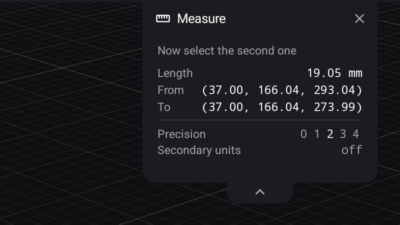
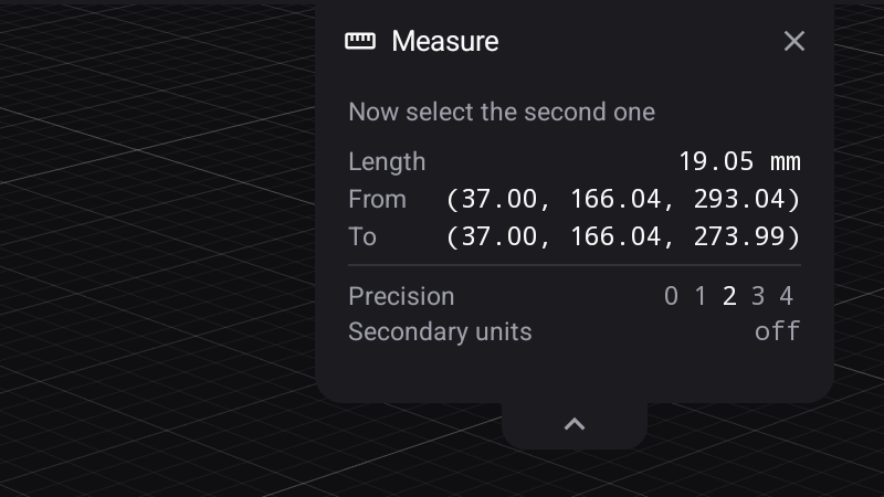
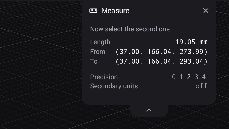
Continue by inspecting curved walls and openings at close range. STEP can retain curved CAD surfaces; the STL copy describes them with facets. A matching straight edge does not establish that these curved regions match equally well. Keep both exports and the original reference for that comparison.
7 · Make a fresh editable copy
Under Canvases, open the original STEP asset's ⋮ menu and choose Re-derive…, then Derive. The saved-file result says Derived; in this example the new STEP body is SOLID (2). This makes another body from the unchanged original. Hide the reference and comparison bodies so the new copy is the one you select for the next feature.
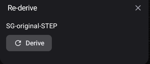
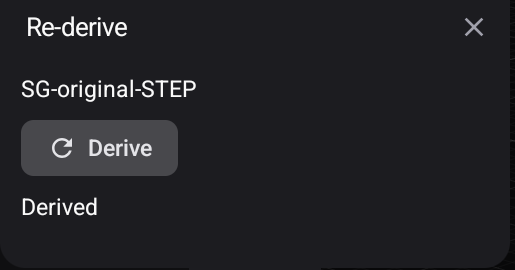
Re-derive is useful when you want to start an edit again without modifying your reference copy. It does not undo the edits on another derived body and does not turn a STEP file into the source app's original sketches or parameters.
Before editing, compare the fresh body with the reference once more. After adding your own features, close and reopen the design and inspect both the shaded result and History. Keep the unchanged source and reference body so you can repeat the comparison later.
8 · Edit the copy and check the saved geometry
Use the fresh SOLID (2) for a small practice feature. This hole belongs to the exercise; it is not a dimension or machining instruction for the original guitar body.
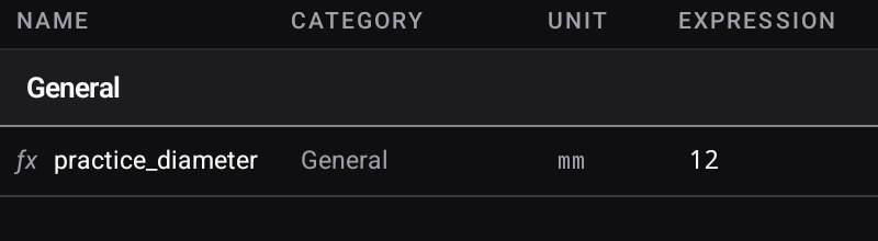
In Parameters, add practice_diameter = 10 mm. Return to Design, choose Hole, and select the large flat top face of SOLID (2), away from the existing routed openings. Use Simple, Diameter practice_diameter, Depth 2 mm and Extent Distance. Leave the placement at the face centre for this exercise, then commit with Hole. Inspect the shallow circular recess before continuing. Close the drawer with ✕ instead if the face or placement is wrong; do not commit a feature on a comparison body.
Change practice_diameter from 10 to 12. Wait for the body to finish rebuilding, then inspect the recess. This is a feature you added to an imported solid; it does not make the original import's unknown dimensions parametric.
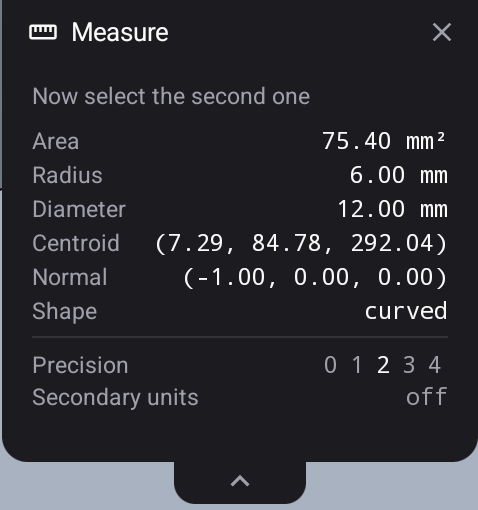
Use Analyze → Measure on the recess's curved wall. Zoom in enough to select the wall rather than its circular edge. The drawer should identify a curved face and show Radius 6 mm and Diameter 12 mm. A changed parameter cell alone would not establish that the solid changed.
Close Measure. Use Undo to return to 10, inspect the smaller recess, then Redo to restore 12. Close and reopen the design normally. Check the parameter and measure the curved wall again: the saved example still reads 12 mm.
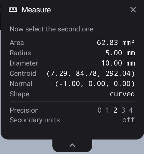
Finally restore practice_diameter = 10, wait for the rebuild, then close and reopen once more. The final example measures Radius 5 mm and Diameter 10 mm. Keep the other bodies hidden while measuring so a coincident reference cannot receive the pick.
The unchanged source assets and the six comparison bodies remain available in the tree. Keep them as references; the practice Hole is on SOLID (2) only.
9 · Place only the edited copy for machining
Make a small practice Bore on SOLID (2), the exact STEP-derived body with the restored 10 mm recess. This checks the path from an imported solid to a posted program; it is not a complete machining plan for the guitar body.
Switch to Manufacturing, create a Tool Run, and select SOLID (2) as its only model. Keep the unchanged original and the six comparison bodies out of this setup. Hiding a body in the design is useful for picking, but the Tool Run's model list is what decides which body it machines.
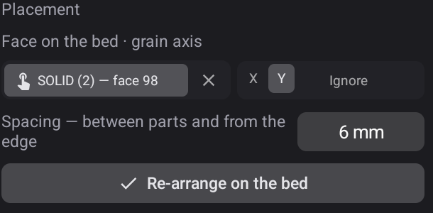
Turn Manufacturing model on. In Placement, select the broad underside as Face on the bed. In this example it is SOLID (2) — face 98; identify the underside by its geometry if your face numbers differ. Set the grain axis to Y, leave Spacing 6 mm for this single part, and choose Re-arrange on the bed. Inspect the top and an angled view: the practice recess should face upward and be accessible to the cutter.
The source file's coordinates are useful for comparing exports. They are not the coordinates in which you must mount the part. The manufacturing placement lays this copy on the bed while the comparison bodies keep their saved design positions.
10 · Give the placed copy stock and a work zero
Under Stock → Shape & Size, choose Relative Box and Add Stock to Sides and Top-Bottom. Use Side offset 2 mm, Top offset 0 mm, Bottom offset 0 mm and Round up to 0 mm. Return to Model & WCS, choose Stock Box, and pick the Top Front-Left corner. Check the corner name in the drawer. Under Program, name the run SG practice bore and choose G54, then confirm the Tool Run.
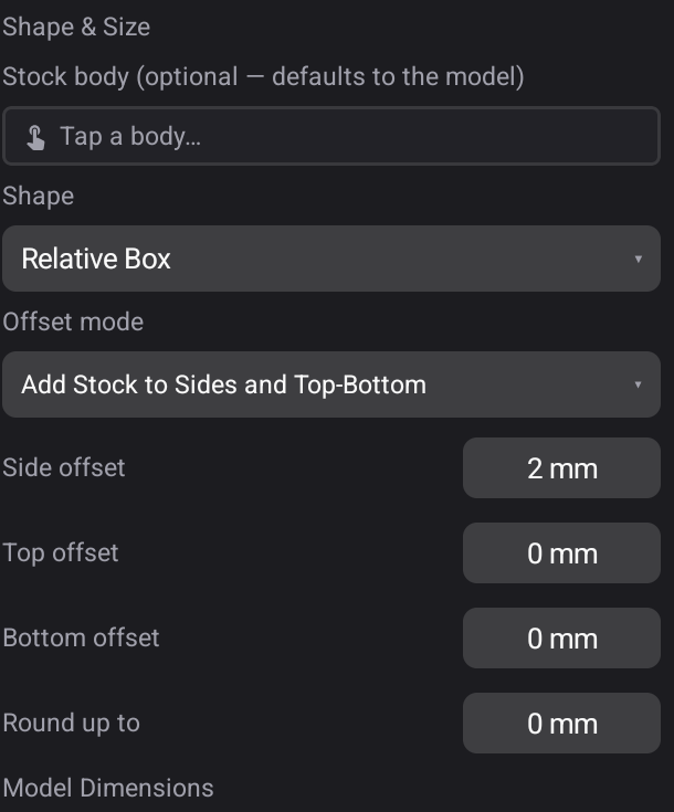
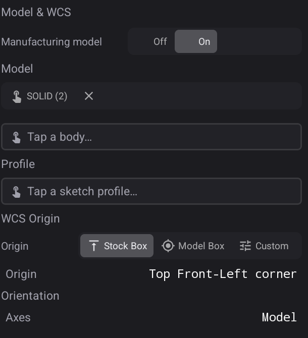
The stock encloses the placed copy. Its top front-left corner is the point that must match your work zero in Control; the original import's origin is not a substitute for that stock corner.
11 · Bore the practice recess from Model top
Choose 2D → Bore and select the curved wall of the 10 mm practice recess. Check that the selection belongs to SOLID (2) and that the Bore contains one hole. A pick on a reference copy or one of the guitar's existing holes would make a different program.
Use these example settings, then choose cutting conditions suitable for your material and machine:
| Section | Setting |
|---|---|
| Tool Library | #201 - 1/4" Square, flat endmill, 6.35 mm, three flutes, T1 |
| Passes | Multiple passes on, radial stepover 3.175 mm, finishing pass on, radial stock to leave 0 mm |
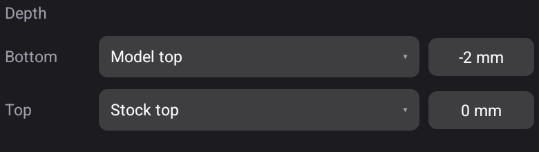
| Heights → Depth | Top Stock top 0 mm; bottom Model top −2 mm |
| Heights → Planes | Retract Stock top +5 mm; clearance Retract +10 mm; feed Top +1 mm |
| Feed & Speed | Spindle 5000 RPM, plunge 333.33, cut 1000, retract 3000 mm/min |
Model top −2 mm means two millimetres below the top of the model in its manufacturing placement. It does not mean two millimetres below the original file's world Z. With no added stock above this model, Stock top and Model top lie at the same height; adding stock above the model would make them different references. Keep the reference and its offset together when checking the depth.
Create Bore 1, or Modify Bore when editing the saved operation. Inspect the helical path inside the practice recess. Its centre is approximately X259.656 Y175.119 relative to this setup's stock corner, and the centreline radius is 1.825 mm: the 5 mm hole radius minus the 3.175 mm tool radius. Those values give you a useful check that the path belongs to the small recess rather than the whole imported body.
12 · Simulate, post and run the practice operation
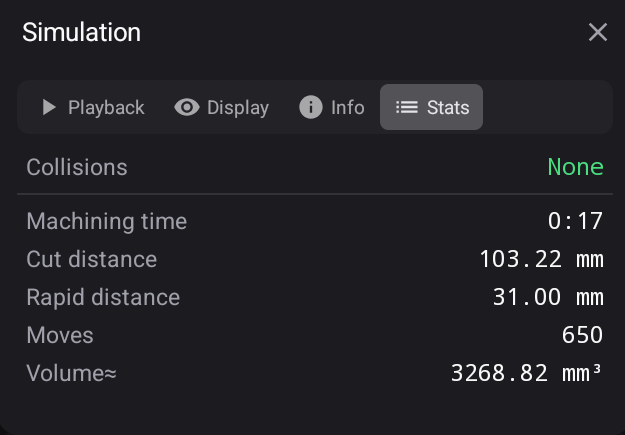
Open Simulate, select All toolpaths, play to the end and inspect the stock and path around the recess. Read Stats → Collisions. This example reports None, 0:17 machining time, 103.22 mm cutting distance and 650 moves. Inspect the depth as well as the absence of a collision; a path at the wrong height can still avoid every obstacle.
Choose Export, select SG practice bore and Bore 1, and post to Import round trip. Check the posted header and coordinates before Run. Here the program uses G21, G90, G54, T1 M6 and S5000 M3. The stock comment is 426.454 × 335.229 × 34.925 mm; the small Bore's cutting bottom is Z−2 mm relative to its top stock corner.
Connect your controller over USB, check its machine profile, and secure a suitable test blank. Home if the machine has homing switches. Fit and measure T1, 6.35 mm, and set G54 at the same stock corner selected in Manufacturing. Verify the tool's cutting length, workholding, zero and clearance; the imported model's own origin is not your work zero.
Open Import round trip in Projects and load the practice file. Loading does not move the machine. Read the preview and Safety result, then open Run and explicitly choose Outline to check the footprint at safe Z with the spindle off. Choose Run → Air Run, check its clearance and suppression settings, and choose Run → Start Project to rehearse the moves. After the rehearsal, choose Run → Air Run again to switch it off and recheck the setup. Choose Run → Start Project for the cut; at the tool-change prompt, confirm Tool Changed — Continue only after the named cutter is secured and measured.
The completion shown below records 660 lines in 58 s, with Feed, Rapid and Spindle overrides at 100%. Its duration includes the tool-change confirmation, so it can exceed the simulation's cutting estimate. Return to History and check the new Completed row and line count. The History image below shows an earlier completed run of the same programme; its elapsed time can differ.


Keep Import round trip in Showcases, with its unchanged originals, comparison bodies, parameter-driven practice feature and checked Tool Run. Export comparison and this shallow Bore prove specific parts of the workflow; inspect machining access, material and workholding separately before planning a real guitar-body job.