 PRIME MOTION
Tutorial: a two-colour inlay sign
A sign in two contrasting woods needs a recessed base and a raised plug. The plug stays attached to a carrier while you machine and glue the lettering. After gluing, remove the carrier and bring the surface flush. This exercise builds the two solids by hand, checks their assembled fit, then prepares their separate machining setups.
The artwork is Prime in Open Sans Bold, 40 mm high, with a five-point Classic Star. The base is 200 × 90 × 18 mm. Its pockets are 2 mm deep with walls 30° from vertical, matching a 60° included-angle V-bit. The entering face of the plug sits 0.1 mm above the pocket floor; a 10 mm carrier holds the raised artwork together.
You will use Text, Extrude, Combine, Interference, Manufacturing model, V-Carve, a shallow 2D Contour, Export and the ordinary running controls. There is no inlay generator. For the geometry behind the fit, see Inlays with existing tools.
1 · Make the base
Create a design named Inlay sign in Showcases. Start a sketch on XY Top and draw a 2-Point Rectangle from the origin into positive X and Y. Keep its edges horizontal and vertical, and dimension the sides to 200 mm and 90 mm. Finish the sketch and extrude it 18 mm as New Body. This is the base; its top is at Z18 and its underside at Z0.
The origin and dimensions matter later. The plug blank must line up with the same rectangle; matching two rectangles by eye can leave a shifted plug even when their sizes look identical.
2 · Place Prime and cut the tapered text
Start a sketch on the base's top face. Choose Text, enter Prime, select Open Sans, Bold, and a 40 mm height. Position its anchor at approximately X30, Y25 mm, leaving space to the right for the star. Finish the sketch.
Arm Create / Extrude and select the text fill. Keep the empty counters inside P and e out of the selection. Choose Cut, a one-sided distance of −2 mm, and taper −30°. Apply and wait for the operation to finish.
The text remains text; this cut uses Text Cut. The negative taper makes the pocket wider at its entry and narrower at its floor. The counter islands have the opposite wall direction, so the surrounding cut narrows on both sides of each stroke.
The offered maximum depth depends on the outline, size and taper. If fine lettering limits the cut too shallow for your inlay, enlarge it or edit its outlines as a sketch. Size the plug from the accepted pocket depth, never from a rejected drag distance.
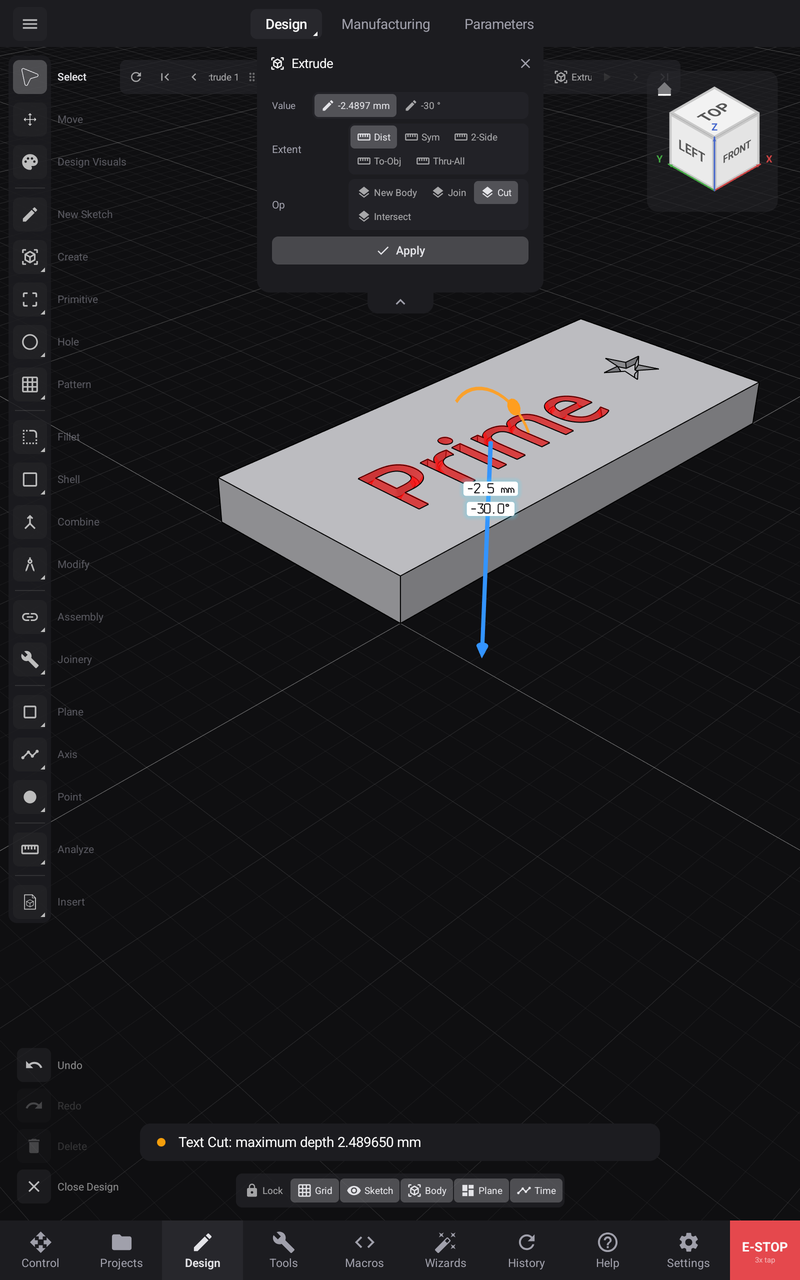
The illustrated rejected drag offers a maximum of about 2.489650 mm for this word and taper. Cancel that preview, then use the intended 2 mm pocket. A red preview is not a completed cut.
Close and reopen the design after an edit. Confirm the depth and taper still agree with the solid. Undo and Redo should restore the corresponding solid as well as the numbers.
3 · Add the Classic Star
Create an offset construction plane 18 mm above XY Top. On it, start another sketch, long-press Polygon and choose Star. Use Classic, 5 points and the 61.8% inner proportion. Place its centre near X175, Y45 mm with an outer radius of about 11.91 mm.
Finish the sketch and extrude the star's closed fill as Cut, −2 mm, −30°. The star is an ordinary sketch profile and uses ordinary Extrude Cut. It does not need a Text record.
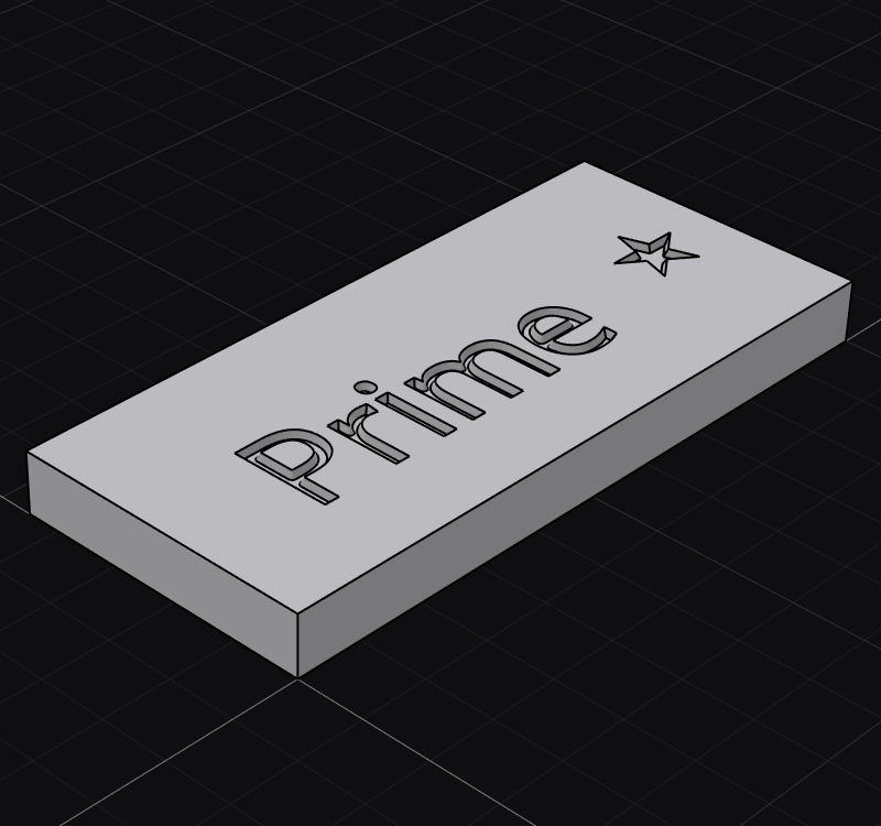
Orbit the shaded base. Check the P bowl, e eye, separate i dot and star tips. The pocket floor is at Z16 mm. Both artwork cuts must have the same intended depth and wall angle before you make the plug.
4 · Make the plug blank and subtract the base
Keep the base in its assembled position. The plug's entering face will be at Z16.1 mm, leaving 0.1 mm above the pocket floor. Its carrier ends at Z28 mm.
- Create another offset plane 16.1 mm above XY Top.
- On it, sketch a 200 × 90 mm rectangle aligned with the base's X/Y origin and edges.
- Finish the sketch and extrude 11.9 mm as New Body. This is the blank.
- Choose Combine → Cut. Select the blank as Target and the pocketed base as Tool.
- Turn Keep Tools on, then apply and wait for the calculation to finish.
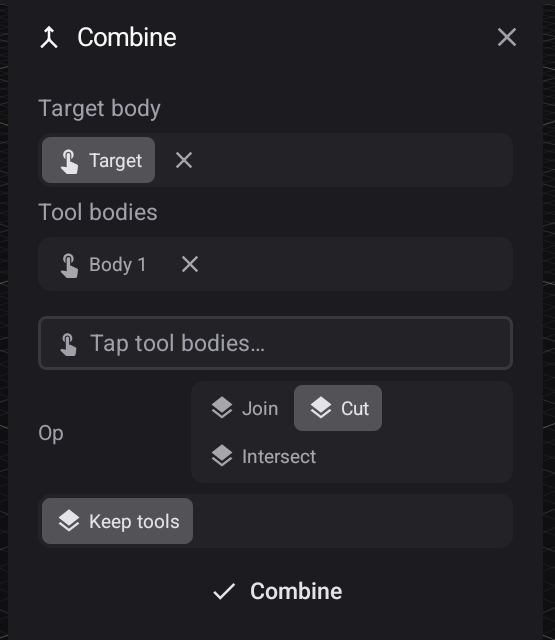
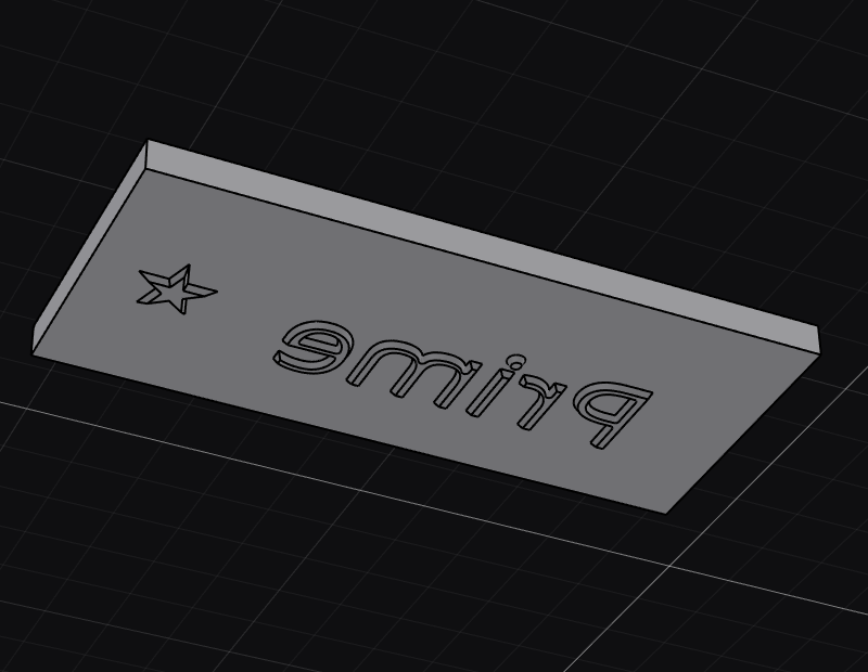
Subtracting the base leaves matching tapered lettering and a star attached to the underside of the carrier. Keep Tools preserves the base so both halves remain available for checking and CAM.
Hide the base and orbit underneath the plug. Check both counter openings and the separate i dot. The counters must be openings in the plug so the uncut islands in the base can enter them.
5 · Check the assembled fit
Restore the base and open Analyze → Interference. Select both bodies, leave Include coincident faces off and compute. The tapered walls are intended to touch; confirm there is no shared volume.
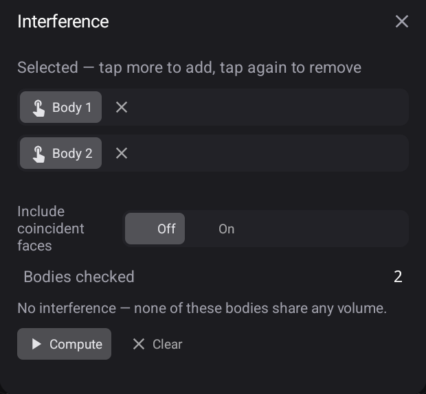
Use Section Analysis through the word to inspect the seat. Here the floor is Z16 and the plug tip is Z16.1, leaving the intended 0.1 mm floor clearance. Zoom and measure the relevant faces; an overview that cannot resolve the gap is not a measurement of it. The clearance is under the entering face, not a sideways offset of the artwork.
This ideal CAD check does not establish a physical glue fit. Cutter tip shape, runout, stock flatness and wood movement still matter. Make a sample before committing valuable material.
6 · Give each half its own Tool Run
Keep both Design bodies in their fitted positions. Manufacturing model provides machining copies, allowing each board to face the cutter without moving the assembled originals.
Create a Tool Run with the intended body as Model, and turn Manufacturing model On. Choose its bed face, arrange it, then inspect the stock and work zero before creating the run.
| Setting | Inlay Base | Inlay Plug |
|---|---|---|
| Model | Pocketed base only | Entire plug and carrier body |
| Face on the bed | Flat underside at Z0 | Flat outside of the carrier at Z28 |
| Grain | X | X |
| Spacing | 6 mm | 6 mm |
| Stock | Relative Box, No Additional Stock | Relative Box, No Additional Stock |
| Stock dimensions | 200 × 90 × 18 mm | 200 × 90 × 11.9 mm |
| WCS Origin | Stock Box, Top Front-Left corner | Stock Box, Top Front-Left corner |
| Work coordinates | G54 | G54 |
Choose the face on Placement, then Arrange on the bed. Check the stock dimensions and work-zero corner after arranging. The plug's raised artwork must point up, towards the cutter. From Top it reads backwards; turning the finished plug back into the assembly restores the readable word.
7 · V-carve the base
Activate Inlay Base. Create a V-Carve with the seven pocket-entry boundaries: P, r, i stem, i dot, m, e and star. Keep the P and e counter rims as islands. This gives seven boundaries and two islands.
Pick the rims at the top entry, Z18, rather than the similarly shaped edges at the pocket floor. An isometric view can make them easy to confuse. Inspect each pick from Top and orbit it before accepting it. A simulation with no collision can still follow the wrong selected rim.
Use the following settings for this example:
| Setting | Base V-Carve |
|---|---|
| Tool | IDC Woodcraft 60° 3/4" V-Bit, 1/4" shank; diameter 19.05 mm, pointed tip |
| Top | Model top, 0 mm |
| Bottom | Top height, −2 mm |
| Multiple depths | On; maximum stepdown 1 mm |
| Maximum stepover | 0.1 mm |
| Pre-pocket | Off |
| Spindle | 14,000 rpm |
| Cut / plunge feed | 2,032 / 635 mm/min |
| Retract / clearance | Stock top +5 mm; retract height +10 mm |
Generate the operation, then simulate it to the end. Inspect the whole word, both counter islands and the star, including the retract moves. The example reaches 21,385 moves, 14:28 estimated machining time and Collisions: None.
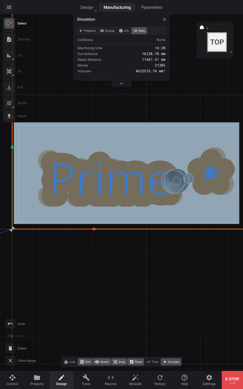
The broad shaded sweep shows the tool footprint. It is not an exact carved-stock picture or a measurement of removed wood. Use the selected rims, heights and tool shape together with the simulation; none of those checks replaces the others.
8 · Clear and V-carve the flipped plug
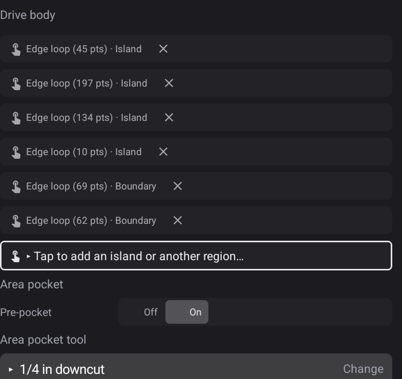
Activate Inlay Plug and create another V-Carve. Use the carrier's outer rectangular edge as the surrounding boundary. Inside it, select the nine artwork tip rims: seven outside artwork loops plus the P and e counter openings. In the assembled Design those tip rims are at Z16.1; in the flipped machining setup they are at the top of the stock.
The seven artwork loops become islands. The two nested counter openings become additional boundaries, because you must remove material inside them. Check the labels in the selection list. The complete region has three boundaries and seven islands. Choose the tip rims, rather than the artwork's wider foot at the carrier face.
Use the same 60° V-bit, spindle, V-carve feeds, 1 mm maximum stepdown and 0.1 mm stepover as the base. Set Top: Model top, 0 mm and Bottom: Top height, −1.9 mm. This removes the background down to the carrier face and leaves the raised artwork.
Turn Pre-pocket On and select Shop cutters 1/4 in downcut, a 6.35 mm flat end mill. For this example its pocket stepover is 3.81 mm, stepdown 0.635 mm, spindle 12,000 rpm, cut feed 1,000 mm/min and plunge 300 mm/min. The flat tool clears the broad background and the P counter. The V-bit then finishes the tapered walls and every region too narrow for the flat tool, including the small e counter.
Clean up the carrier's perimeter
A V-carve inside a closed rectangular boundary leaves a raised rim along that boundary. Remove it, or the border will stop the carrier from coming down onto the base.
Add a shallow 2D Contour on the carrier's outer rectangle. Use the same 6.35 mm downcut, set Side: On, Top: Stock top, 0 mm and Bottom: Selected contour, 0 mm. Select the outer edge at the carrier face, so that the resulting bottom reads −1.9 mm. Leave Tabs Off. Use 12,000 rpm, cut 1,000 mm/min and plunge 300 mm/min.
The cutter is centred on the perimeter, so half of it runs outside the stock. Leave room around the board for its radius and leads, and keep clamps out of that path. It is a shallow cleanup, not a through cut: the 10 mm carrier stays whole.
Simulate the whole plug
Simulate All toolpaths for the plug and step to the end. This example reports 82,274 moves, 69:08 estimated machining time and Collisions: None. Look at it from Top with Rapids and Leads hidden: the artwork reads backwards, the background is cleared, and the P bowl and e eye are cleared as well. The letters themselves stay untouched.
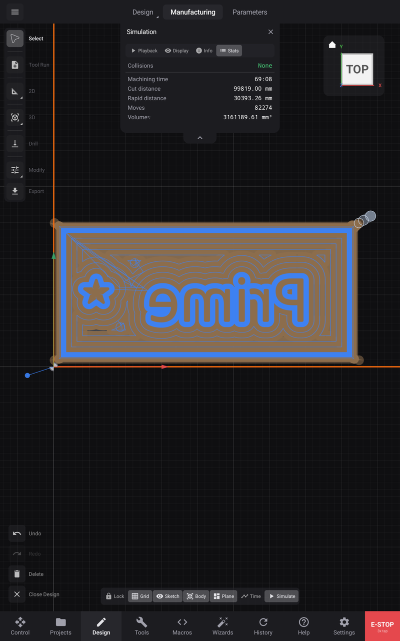
If a counter shows no paths inside it, check the region list again. A counter opening that has been picked as an island, or not picked at all, is left standing and the plug will not seat.
9 · Export each half
Export the base and the plug as separate jobs, so that each board keeps its own work zero and file order. When a half's toolpaths are finished, open Export, keep only that Tool Run's operations ticked, and give the project its own name: here Inlay sign base and Inlay sign plug. Exporting a selection under an existing project name replaces that project's file list.
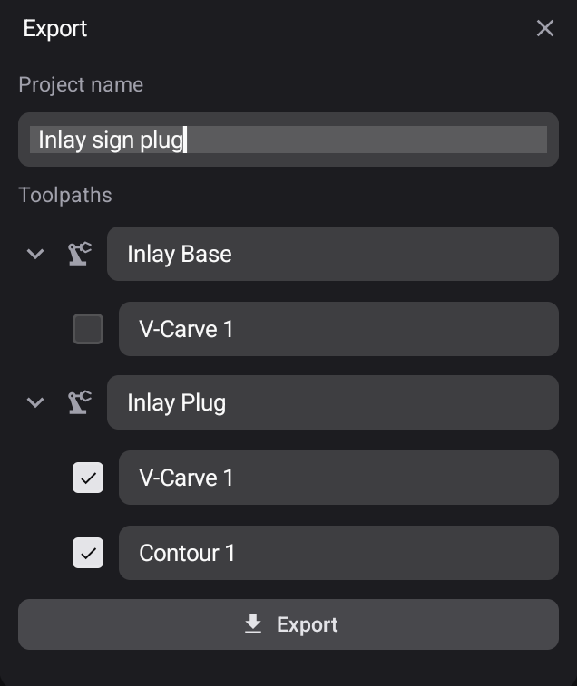
The base produces one V-Carve 1 file. The plug produces three, in this order:
- V-Carve 1 (1 pocket) — the flat tool clears the background and the P counter.
- V-Carve 1 (2 v-carve) — the V-bit finishes the walls and the narrow regions.
- Contour 1 — the flat tool cleans up the perimeter.
The punctuation in a saved filename may differ. Check the tool and operation of each file rather than assuming every file named V-Carve uses the V-bit. Here the plug files call T1, T2 and T3; the first and third use the same cutter, but each keeps its own tool number.
Check the units, work offset and depths before running. Both jobs use G21 and G54. The base reaches Z−2 mm; the plug files reach Z−1.9 mm and retract to Z15 mm. The perimeter cleanup leads in beyond the stock edge, so check the cutter's full width against your clamps, not only its centreline.
10 · Rehearse and cut the files on your machine
Connect the controller over USB, select the matching machine profile, and home if homing switches are fitted. Secure each blank in its own setup with room for the Z15 retracts and the full cutter and holder width. Fit and measure the tools the setup calls.
On Control, set G54 at the stock corner used by that setup's Tool Run. Probe or jog and zero using the ordinary controls; verify X, Y and Z against the actual blank. Re-establish the correct zero when changing from the base to the plug blank.
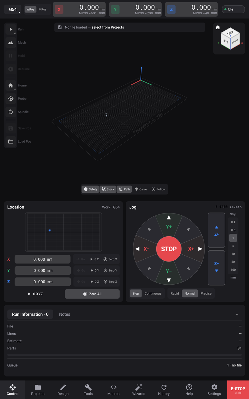
Open Projects, choose the job and press Run on its Tool Run. Its files are queued in posted order; loading does not move the machine. Check the preview and Safety result. With the machine clear, open Run and explicitly choose Outline to trace the footprint at safe Z, spindle off. Then choose Run → Air Run, verify its clearance and spindle suppression, and choose Run → Start Project to rehearse all the moves. Choose Run → Air Run again to switch it off afterwards. Repeat these checks for the other blank's setup before cutting it.
Measure every tool the job calls on Settings → Tooling. A tool whose length has never been measured on this machine is refused at its tool change; a wrong length puts the following Z moves at the wrong height. Recheck the blank, zero and cutter before the cut.
Choose Run → Start Project for the cut. Before each file the queue stops for its tool. Check the requested tool number, type and diameter, fit that cutter, then choose Continue and Tool Changed — Continue.
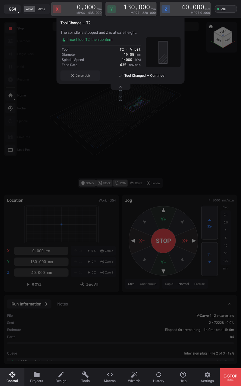
Watch every file to the end, and confirm the full line count and Completed in History. A loaded file or a clean simulation is not a completed run.
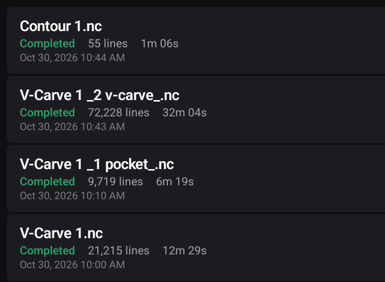
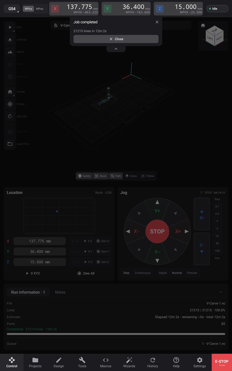
In this walkthrough the base completed 21,215 / 21,215 lines in 12m 02s.
A complete plug run recorded 9,719 / 9,719 lines in 6m 19s, 72,228 / 72,228 in 32m 04s and 55 / 55 in 1m 06s.
The base example used 100% feed at first, then 200% through completion; the override was restored to 100% afterwards. The recorded plug example used 200% for most of its run, then 100% before its final file finished. Rapid and Spindle remained at 100%. The elapsed times describe those overrides; they are separate from the simulation estimates. Begin your setup at 100% and use cutting conditions suitable for your material and cutter; the recorded override is not a feed recommendation.
After the last file, return to the design. Close it, reopen it, and check each Tool Run's model, stock, work zero and toolpaths. Keep the assembled solids for the final fit check.
11 · Fit and glue the inlay
Prepare flat stock and prove the workholding, zero and cutter shape on a sample. Machine the base, then the mirrored plug in its own setup. Check that the counter openings and the perimeter are clear before dry-fitting. The plug should seat on its tapered walls and keep the planned floor clearance.
Glue with the carrier supporting the fine artwork. Once the glue has cured, remove the carrier and bring the plug flush without cutting below the base's finished surface. A completed program does not prove that the wood has seated or that the glue joint is sound.
Changing the font, size, depth or taper changes the geometry. Recheck the Text Cut depth, remake the matching plug, regenerate the affected toolpaths, simulate and export fresh files. Treat the pocket and the plug as one design decision.