 PRIME MOTION
Tutorial: a revolved catch-all tray
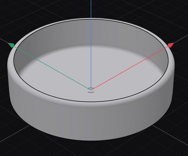
A revolved part starts with its cross-section. Draw the material on one side of an axis, then turn that section around the axis. This makes the outside, inside and floor together, with dimensions that describe the finished part directly.
You will make a tray about 100 mm across and 24 mm high. Its floor and straight wall are 4 mm thick. Two fillets soften the outside rim and inside floor corner. Manufacturing covers the surfaces reachable from above; the underside and any remaining workholding material need another setup.
Start with the fixture plate if you have not yet created a design, entered a parameter expression, selected a cutter or run a posted file.
1 · Name the design and its dimensions
In Design, open Showcases, choose New design, and name it Revolved tray. In Parameters, add these values in millimetres:
| Name | Value | What it controls |
|---|---|---|
| tray_diameter | 100 | Outside diameter before the rim fillet |
| tray_height | 24 | Overall height |
| wall | 4 | Straight wall thickness |
| floor_thickness | 4 | Floor thickness |
| rim_radius | 3 | Outside rim and inside floor fillets |
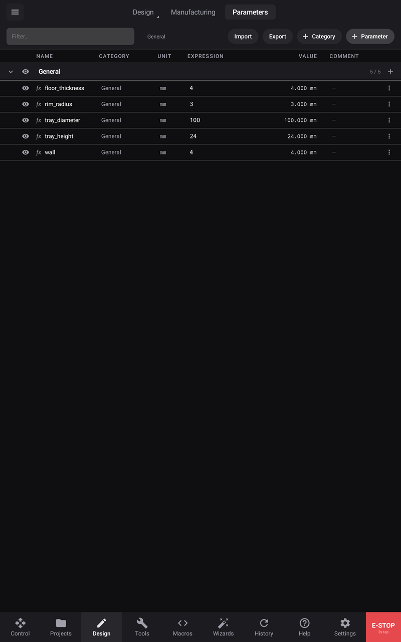
Use floor_thickness as the parameter name; floor is a reserved function name. Keep the cross-section dimensions tied to these names so you can change the tray without redrawing it.
2 · Draw the material in cross-section
Start New Sketch on XZ Front. The sketch stands upright: X is the radius and Z is the height. The revolve axis will pass through X = 0.
Draw six connected straight segments in this order. The coordinate pairs below are X and Z in millimetres; they describe the intended section, rather than screen positions to estimate by eye.
| Corner | X | Z |
|---|---|---|
| Bottom at the axis | 0 | 0 |
| Outside bottom | 50 | 0 |
| Outside top | 50 | 24 |
| Inside top | 46 | 24 |
| Inside floor | 46 | 4 |
| Floor at the axis | 0 | 4 |
Close the last corner back to the first. This is a single closed outline of the material. The long bottom line, outside wall, rim, inside wall, inside floor and short line at the axis should all be visible. The open space above the floor becomes the bowl.
Apply Horizontal to the three horizontal segments and Vertical to the three vertical segments. Join adjacent endpoints with Coincident where they are not already joined. A picture that looks closed can still contain a small gap; confirm that the material region has a fill.
Bind these dimensions with the expression keypad:
- Bottom radial length: tray_diameter/2.
- Outside vertical length: tray_height.
- Short top radial length: wall.
- Short vertical length at the axis: floor_thickness.
These four dimensions leave the inside radius and wall height to follow from the closed shape. Avoid fixing an entire line that must change length: Fix/Lock would prevent the dimension from doing its job. If you constrain the wrong entity, undo that constraint while the sketch is active, then select the intended endpoints or edge again.
Draw a separate vertical construction line along the axis, extending beyond the section. Switch Construction on for that line and keep it on X = 0. The axis is a reference for the revolve; it must not add another material region. Choose Finish Sketch.
3 · Revolve the section
- Open Create → Revolve.
- Select the filled material cross-section as the profile.
- Select the vertical construction line as the axis.
- Use One direction, 360°, and New Body.
- Apply Revolve and orbit the result.
Check for an open bowl, a solid floor and shaded outside faces. If the profile is hard to pick, check the Sketch display chip and the sketch folder's visibility. A hidden reference cannot be picked simply because its name remains in the tree.
The section touches the axis along its floor, so the revolution closes the centre. Do not revolve a rectangular ring that leaves the centre empty if you intend to make a tray with a bottom.
4 · Round two useful corners
Choose Fillet and select the outside top rim and the circular corner where the inside wall meets the floor. Set the radius to rim_radius, then apply it.
Leave the inside top rim sharp in this example. Two opposing 3 mm fillets do not fit across a 4 mm wall. The inside floor fillet is useful for ball-nose finishing, while the outside rim fillet removes a sharp handling edge.
Inspect both selections before applying. An edge seen through the bowl can be a different circular edge from the one at the front of the view. Orbit or zoom to separate them instead of accepting an ambiguous pick.
5 · Check the section and a parameter change
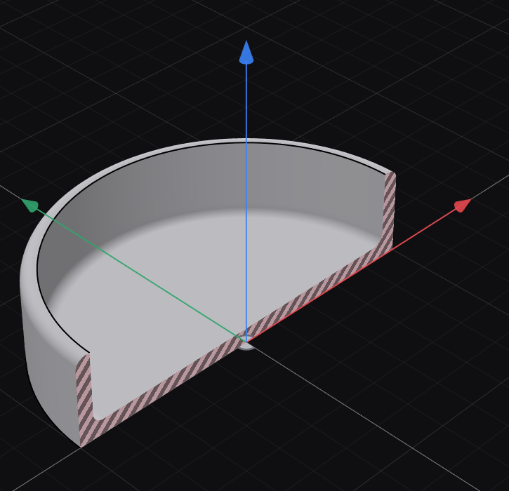
Open Analyze → Section Analysis, select XZ Front, and inspect the tray at zero offset and zero angles with the hatch on. Temporarily hide Body if the solid obscures the origin plane picker, then show the body again to inspect the section.
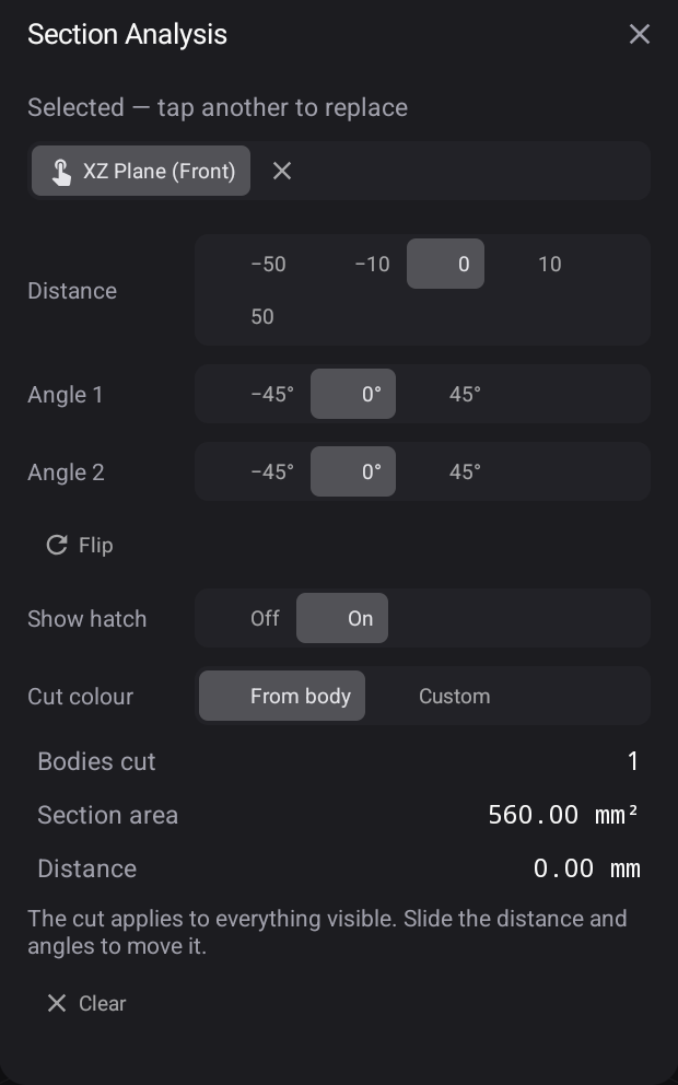
Check the straight wall and floor against the 4 mm dimensions. The fillet changes the local corner shape, so do not measure its curved band as though it were the straight wall. The hatched section also makes an accidental through-hole or missing floor easy to spot. Collapse the drawer to inspect the complete section without covering the back wall.
Minimum Radius can help identify concave regions relative to a chosen tool radius. Its result is an analysis aid; do not treat one reported radius as a guarantee that every local blend or surface is accessible to that cutter. See Analysis.
In Parameters, change tray_height from 24 to 26. Return to Design and inspect the taller wall. Change it back to 24, inspect again, then close and reopen the design. Check the shaded body, its features and its History before moving on to toolpaths.
6 · Set up the blank from above
Create a Tool Run called Tray Top with the tray body selected as its model. Use these settings:
| Setting | Value |
|---|---|
| Stock shape | Relative Box |
| Side offset | 2 mm |
| Top offset | 1 mm |
| Bottom offset | 0 mm |
| WCS origin | Stock Box, Top Front-Left corner |
| Work coordinates | G54 |
| Axes | Model axes |
Pick the top front-left stock corner glyph in the view and confirm its name in the drawer. The work zero must represent the same place when you load the posted files in Control.
This setup reaches the bowl, rim and accessible outside surfaces from above. It does not machine the underside or establish how the part is clamped. Leave a practical way to hold the blank and plan the second setup before cutting a physical part.
7 · Rough with a flat end mill
Open 3D → 3D Adaptive Clearing. Select the tray and deliberately choose the Amana Tool 45213, a 6 mm flat cutter, through Favorites. If it is not a favourite yet, find and star it in the tool selector first.
For this example, set:
| Setting | Value |
|---|---|
| Max stepdown | 3 mm |
| Fine stepdown | 1.5 mm |
| Optimal load | 2.4 mm |
| Radial and axial stock to leave | 0.5 mm |
| Boundary | None |
| Top | Stock top, offset 0 mm |
| Bottom | Model bottom, offset +4 mm |
The bottom is at the tray's inside floor height. A positive offset from Model bottom places that limit above the underside. It does not mean cutting 4 mm below the model.
Create the operation and inspect the path inside the bowl as well as around the outside. Roughing should remove the bowl's upper material before approaching its floor. Stock to leave reserves material for the finishing cutter.
8 · Compare two finishing strategies
A flat cutter leaves steps on curved surfaces. A ball-nose cutter follows those surfaces more closely, and a smaller stepover reduces the spacing between its passes at the cost of a longer path.
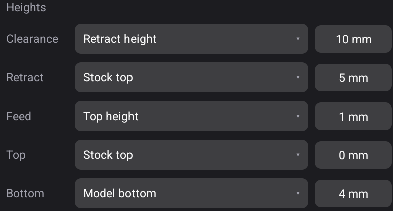
Create Parallel after the rougher. Choose Amana Tool 46479, nominally a 6 mm ball cutter; the catalogue selection displays about 5.99 mm. Use Both ways, a displayed stepover of 0.35 mm, 0.01 mm tolerance, no stock to leave, no boundary, and a bottom at Model bottom +4 mm.
Check the height references explicitly: Stock top +0 mm and Model bottom +4 mm. In this stock-corner setup, the inside floor is at Z−21 mm in the posted program.
Simulate the rougher and Parallel in that order. Inspect the remaining material and the curved wall, then record the time and the appearance of the finish. A finishing path simulated by itself starts from the full blank, so it does not show the same material state as finishing after roughing.
For the comparison, remove the Parallel operation through its tree menu and confirmation, then create Scallop with the same cutter, stepover, tolerance, allowance and bottom limit. Use Use boundaries and inspect the resulting path. Simulate the rougher followed by Scallop.
Compare the two results on the same tray and stock. Retain the strategy that gives the coverage and finish you need; recreate Parallel with the recorded settings if you prefer it. Do not run both full-surface finishers just because both were demonstrated. A longer machining time alone does not prove a better surface.
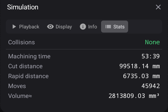
On the example tray, the rougher followed by Parallel reported 53:39 and 45,942 moves, with Collisions: None:
Replacing Parallel with Scallop reported 61:00 and 132,919 moves, again with Collisions: None:
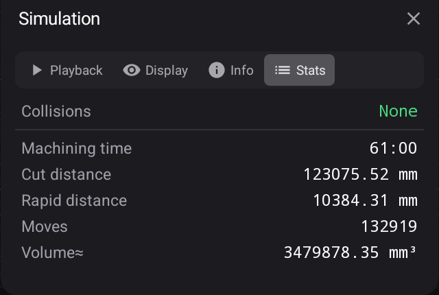
These are the complete roughing-plus-finishing totals from the same stock setup. They show the extra travel and moves in this Scallop path; inspect the material and coverage as well before choosing a finisher for your part.
For the stock comparison, keep Stock on in Display, choose All toolpaths, and use ⏭ to reach the end. Temporarily turn the viewport Body chip off so the model does not cover the remaining stock. Turn Rapids and Leads off, then inspect from Top and an isometric view. The blue cutting lines remain visible, including those from roughing.
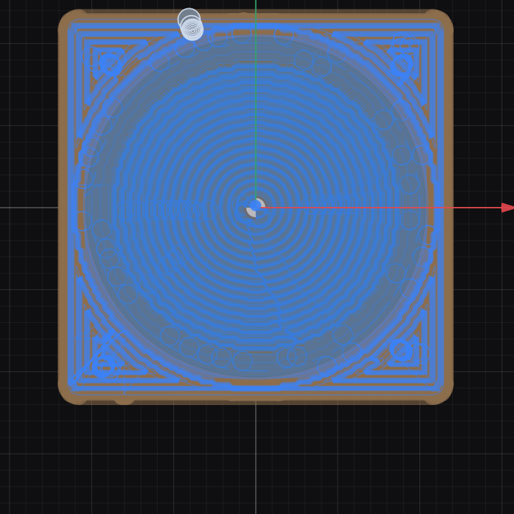
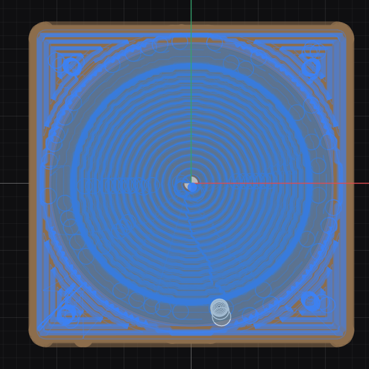
Compare the bowl floor, rim and remaining outer stock. These overviews help check coverage; the dense cutting lines limit how much fine surface detail you can judge. Turn Body back on after inspecting the stock.
See 3D strategies for the strategy controls and Simulation for the playback and display controls.
9 · Inspect the complete tool run
Open Modify → Simulate and choose All toolpaths with the rougher followed by the retained finisher. Play the simulation and inspect the bowl, floor, rim and outside surfaces. Check Stats → Collisions before exporting. Investigate any collision or unexpected rapid descent; a completed path calculation by itself is not permission to cut.
After any model edit, reopen the affected operations and apply or regenerate them, then repeat the whole tool run simulation. The posted files must come from the geometry and settings you checked.
10 · Post, rehearse and cut on your machine
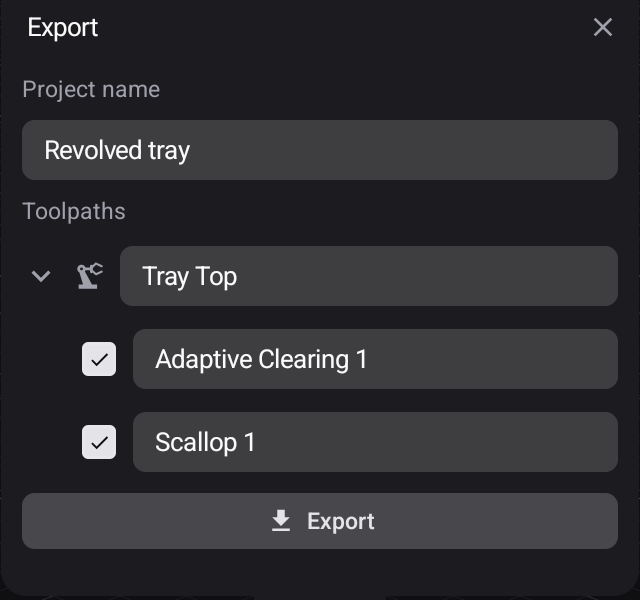
Open Export, name the project Revolved tray, and select the roughing and retained finishing operations under Tray Top. Export them, then open the project in Projects and check their order and tool identities.
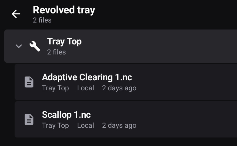
Connect your controller over USB, check its profile and travel, and home if it has homing switches. Secure the blank so the bowl and outside paths clear the clamps; the underside needs its own later setup. Fit and measure the requested cutters. In Control, set G54 at the same stock corner used in Manufacturing, and verify zero, cutting length and clearance.
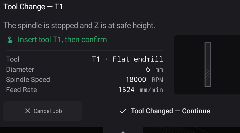
Use Run Project from the tray project. Loading does not move the machine. Check the preview and Safety result, then open Run and explicitly choose Outline to trace the footprint at safe Z with the spindle off. Choose Run → Air Run, verify its clearance and spindle suppression, and choose Run → Start Project to rehearse every move. Choose Run → Air Run again to switch it off after the rehearsal. Recheck the setup, then choose Run → Start Project for the cut, reading each actual work-zero and tool-change prompt before confirming it.
The Control layout adapts to the tablet's orientation. The same running job remains active while you change the view; read the filename and progress rather than treating a moving preview as completion.
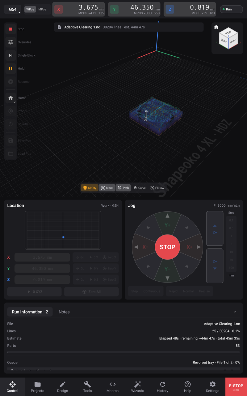
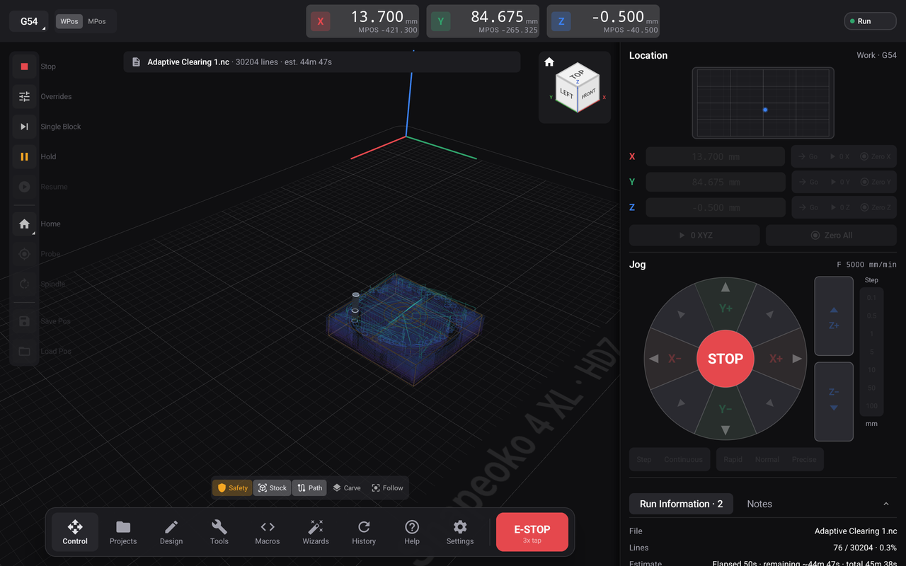
The recorded example used a 200% feed override for most of the run, then returned to 100% before the final file finished. Your elapsed time depends on the program, machine rates and overrides; it is separate from the simulation comparison. Start your setup at 100% and choose cutting conditions for the actual material; the recorded override is not a recommendation.
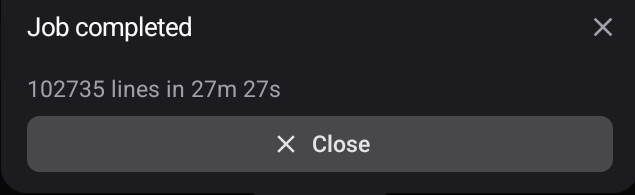
After roughing, close the individual Job completed summary if it covers the file-transition prompt. File Complete — Tool Change names the completed rougher and the next finishing file.
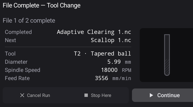
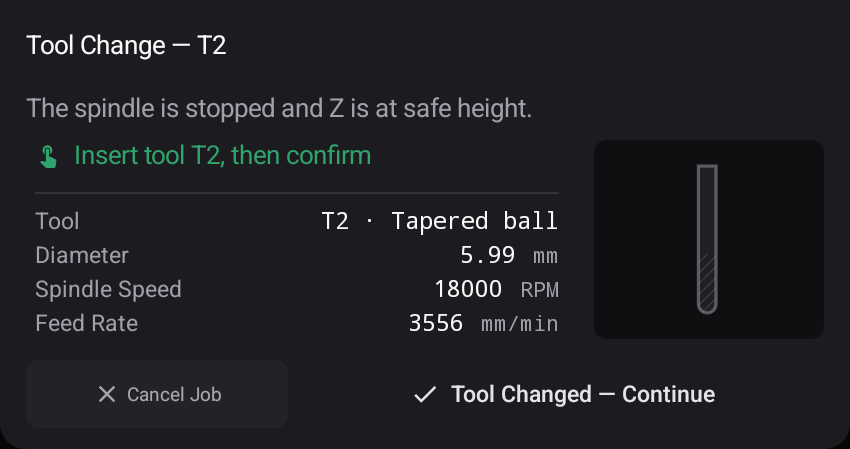
Choose Continue when ready. Read the next Tool Change prompt, wait for the machine to be secured, and confirm Tool Changed — Continue only after the named tool is fitted.
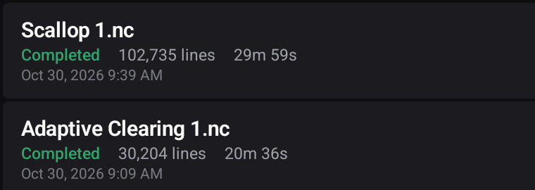
Check the completed entries in History when both files finish. The Scallop completion summary below records 102,735 lines / 27m 27s, with Feed at 200% for most of the run and restored to 100% before completion. The History example shows an earlier run: 30,204 lines / 20m 36s for Adaptive Clearing and 102,735 lines / 29m 59s for Scallop. These posted programmes respect the checked finishing bottom. Elapsed times depend on the recorded overrides; compare line counts and completion status as well as time.
The detailed zeroing and file-transition sequence is in the fixture plate tutorial and Project runs. An example completion record does not establish that your blank is secure or that its underside has been finished.
Keep Revolved tray in Showcases. The next tutorial uses several section profiles to make an organic handle rather than revolving one section around an axis.